I'm looking for a simple way to switch between two voltages for EPROM programming.
The chips I'm programming at present are S87C652, which are OTP 8051 derivatives and need Vpp to be switched between logic '1' and 12.75V, at 10 or 20mA (from memory).
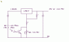
I started making an 8751 programmer many years ago but stalled on this aspect and hand drew one of my very few PCBs which I still have. Then I used a relay because I couldn't think of anything else but I though it would cause problems. I don't think I ever used it on a real chip because I wanted to burn a windowed 8751 and didn't have an eraser so I shelved it.
Later I made a programmer for PIC 16C84 using an analogue switch for Vpp control which worked but felt like the wrong way to use them. Maybe it's OK though, I don't know.
There may be a simple solution using transistors but I'm still vague about using them. I don't really want a solution which is tied to a fixed value for Vpp as this varies from chip to chip. Maybe using two FETs would work as I believe their 'on' resistance is low.
I'm assuming I'll use an external variable PSU for Vpp and have a software controlled switchover between 5V and Vpp but willing to consider other solutions if simple and cheap.
The chips I'm programming at present are S87C652, which are OTP 8051 derivatives and need Vpp to be switched between logic '1' and 12.75V, at 10 or 20mA (from memory).
I started making an 8751 programmer many years ago but stalled on this aspect and hand drew one of my very few PCBs which I still have. Then I used a relay
because I couldn't think of anything else but I though it would cause problems. I don't think I ever used it on a real chip because I wanted to burn a windowed 8751 and didn't have an eraser so I shelved it.Later I made a programmer for PIC 16C84 using an analogue switch for Vpp control which worked but felt like the wrong way to use them. Maybe it's OK though, I don't know.
There may be a simple solution using transistors but I'm still vague about using them. I don't really want a solution which is tied to a fixed value for Vpp as this varies from chip to chip. Maybe using two FETs would work as I believe their 'on' resistance is low.
I'm assuming I'll use an external variable PSU for Vpp and have a software controlled switchover between 5V and Vpp but willing to consider other solutions if simple and cheap.
Last edited: