Continue to Site

Welcome to our site!

Electro Tech is an online community (with over 170,000 members) who enjoy talking about and building electronic circuits, projects and gadgets. To participate you need to register. Registration is free. Click here to register now.

  • Welcome to our site! Electro Tech is an online community (with over 170,000 members) who enjoy talking about and building electronic circuits, projects and gadgets. To participate you need to register. Registration is free. Click here to register now.

Voltage Rating for Unpolarised Capacitor Made From Two Polarised Capacitors

Status
Not open for further replies.

ACharnley

Member
HI,

Just need confirmation for this, did try Google but nothing came up.

If I take two 25V electrolytics and wire them back to back would the voltage rating still be 50V (as it would if they were not back to back)?

My understanding is one is operating as a short so the other would actually take the full 50V?

Thanks!

Andrew
 
05.png


If you are doing something involving high currents in the capacitors (such as AC motor starting) , watch out for their "ripple current" rating. An electrolytic being used this way is completely charged/discharged each cycle.
 
Last edited:
I wouldn't count on it. If the reverse polarity capacitor really behaves as a short (and I'm not saying that it does), the other capacitor would try to take the full 50V being applied to it when it can only handle 25V.

If the reverse polarity capacitor does not behave as a short, then the voltage difference will try to be split across the two and the reversed cap will try to take -25V (or some amount of reverse voltage) when it can't handle it.

Seems like the combined rating can never be 50V no matter how you look at it.
 
...
Seems like the combined rating can never be 50V no matter how you look at it.
Look at the simulation I posted. With +-25Vac (50V swing) applied, lower capacitor, C2 sees 0 to +25V (minus one diode drop), while the upper capacitor C1 sees 0 to -25V (minus one diode drop). If the capacitors are rated for 25V, then you cant exceed that...
 
So in summary it does not double the voltage (as one it acting as a short).

Somewhat related, electrolytics are meant to be damaged when connected in reverse, so how does that not occur here?
 
So in summary it does not double the voltage (as one it acting as a short).

Somewhat related, electrolytics are meant to be damaged when connected in reverse, so how does that not occur here?

He put steering diodes across them - so they aren't connected in reverse.

However, it's common practice to simply place two electrolytics in series to make a non-polarised capacitor for speaker crossovers - but in this case there's never any static DC across them.
 
Ah I did wonder what those diodes were for.

However with AC one of the capacitors is still in short for half the cycle, just the voltage is varying. So why aren't steering diodes used here? Is it because the time it's in short is minimal?
 
Where "here" is an AC voltage such as Nigel's example.
I think it's because the properly biased capacitor takes all the charge so the reversed capacitor does not charge up at all. Nigel never said anything about the applied voltage exceeding the rating of one capacitor (whcih seems to be your ultimate concern).
 
It was my original concern but now I'm wondering if my design needs additional diodes. I'm only dealing with AC, but I can't see why they wouldn't be needed for AC if they're needed for DC. The only difference that I can see is they may not charge fully (frequency dependent) which limits how much charge goes through on the short.
 
I think that two electrolytics connected inverse-series end up biased as though they had the steering diodes I showed. The forward biased leakage is different than the reversed-biased leakage, so they end up biased just like my simulation. With the diodes, the bias is accumulated on the fist cycle, while without the diodes, it would take many cycles...
 
LTspice shows the diodes have no effect, at least with AC, so it's easier to follow the capacitor short than go through the diodes?
 

Attachments

  • Screenshot_2018-08-28_07-04-09.png
    Screenshot_2018-08-28_07-04-09.png
    40.2 KB · Views: 88
The reason that there is zero current is because the right end of the capacitor network is floating. Post the entire circuit.
 
No there is current through the caps, just not through the diodes.
Wrong! It is the current in the diodes that prevent reverse currents (that damage the polarized layer inside the electrolytic capacitor) from flowing in the capacitor. To say this another way, the diode clamps the reverse voltage that would otherwise appear across the capacitor, depolarizing it.
Unable to post the whole circuit (legal) sorry.
What BS! You do not have to post the "whole" circuit; just enough to provide a realistic simulation of what the series capacitors are subjected to.

If an electrolytic capacitor is reversed-biased, it breaks down the polarized layer, punches through, and leaks. Spice does not model this behavior directly (a Spice Capacitor is a pure, idealized device). So follow along Nigel Goodwin; you might learn something about what a simulator can show.

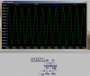
First with only "ideal" capacitors, that unlike real electrolytics, exhibit no real-world depolarization behavior:
5.png
V(x) is the +-20V applied AC voltage, and appears across C1 and C2 in-series.
V(y) is the voltage that appears across C2. Note that it reverses the polarity across C2 by -10V during every cycle, depolarizing it.
Y(x)-V(y) is the voltage that appears across C1. Note that it reverses the polarity across C1 by -10V during every cycle, depolarizing it.

To prevent C1 and C2 from reverse polarity, look what happens if we pre-charge both capacitors to 10Vdc before we apply the sine wave. In Spice, this is done with the .IC (Initial Conditions) directive:
5a.png
Notice that the reverse polarity problem is solved.
V(y) is the voltage that appears across C2. Note that the polarity across C2 is always positive; no depolarization.
Y(x)-V(y) is the voltage that appears across C1. Note that the polarity across C1 is always positive; no depolarization.

So how do we "automatically" pre-charge the capacitors? That is where the diodes come in. Here is another simulation run with the diodes added. I also shortened the time frame, so we can see what happens during the first few cycles of the applied AC wave.
5b.png
Notice that the reverse polarity problem is solved because the diodes "rectify" the applied AC and precharge the capacitors.
V(y) is the voltage that appears across C2. Note that the polarity across C2 is always positive within one diode drop; no depolarization if the electrolytic will tolerate a small reverse bias of 0.6V. I(D2) shows the current through D2.

Y(x)-V(y) is the voltage that appears across C1. Note that the polarity across C1 is always positive within one diode drop; no depolarization if the electrolytic will tolerate a small reverse bias of 0.6V. I(D1) shows the current through D1.

Note that I(D1) is much larger than I(D2). This is because V1 went positive on the first cycle, so D1 does mostly all the work of charging both capacitors on the first half-cycle of AC. There is an assymptotically decreasing bit of current in both diodes on subsequent half-cycles. After hundreds of cycles, those current pulses will continue, but they are tiny, only having to replace the charge lost due to a bit of leakage in the capacitors.

For those that think it is ok to make an AC capacitor without adding the diodes will have to convince me and themselves that the capacitor maker thinks it is ok to reverse bias the electrolytics repeatedly, cycle-by-cycle, allowing the capacitor to repeatedly break down.

Read page 13 of this CD Application guide...
 
Last edited:
Status
Not open for further replies.

Latest threads

New Articles From Microcontroller Tips

Back
Top