Continue to Site

Welcome to our site!

Electro Tech is an online community (with over 170,000 members) who enjoy talking about and building electronic circuits, projects and gadgets. To participate you need to register. Registration is free. Click here to register now.

  • Welcome to our site! Electro Tech is an online community (with over 170,000 members) who enjoy talking about and building electronic circuits, projects and gadgets. To participate you need to register. Registration is free. Click here to register now.

voltage levels for CMOS

Status
Not open for further replies.

PG1995

Active Member
Hi,

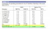
In this , seems to say the same thing that some CMOS circuitry could work even at 15 V or 18 V.

Then, I read this attached text #2 which seems to suggest that a single CMOS circuitry could operate over a wide range of supply voltages.

"An advantage of CMOS is that it can operate over a wider range of dc supply voltages (typically 2 V to 6 V) than bipolar and, therefore, less expensive power supplies that do not have precise regulation can be used. Also, batteries can be used as secondary or primary sources for CMOS circuits. In addition, lower voltages mean that the IC dissipates less power. The drawback is that the performance of CMOS is degraded with lower supply voltages. For example, the guaranteed maximum clock frequency of a CMOS flip-flop is much less at VCC = 2 V than at VCC = 6 V."

Is there a contradiction? Perhaps, there exists some CMOS which could accept a wide range of supply voltages as suggested in the text #2 and others could only work on defined set supply voltages as suggested by text #1?

Thank you for the help!
 

Attachments

  • cmos_voltage1.jpg
    cmos_voltage1.jpg
    263.5 KB · Views: 225
  • cmos_voltage2.jpg
    cmos_voltage2.jpg
    91.4 KB · Views: 218
Last edited:
The 4000 series CMOS logic can handle 15 (absolute max is 18) but most other logic levels are 5v and below. Some newer types on tiny, tiny SMD chips runs as low as 0.7v.
 
The 74HC series CMOS logic have the following supply requirements :-
74HC Supply: 2 to 6V, small fluctuations are tolerated.
74HCT Supply: 5V ±0.5V, a regulated supply is best.
 
Thank you!

"An advantage of CMOS is that it can operate over a wider range of dc supply voltages (typically 2 V to 6 V) than bipolar and, therefore, less expensive power supplies that do not have precise regulation can be used. Also batteries can be used as secondary or primary sources for CMOS circuits. In addition, lower voltages mean that the IC dissipates less power. The drawback is that the performance of CMOS is degraded with lower supply voltages. For example, the guaranteed maximum clock frequency of a CMOS flip-flop is much less at VCC = 2 V than at VCC = 6 V."

I will add the following to text above (from post #1) to make it more clear.

In other words, you can find CMOS ICs with the same functionality but having different supply voltage requirements. For example, if you are working on a circuit with, say 3V supply voltage, you can get a CMOS IC which could work on 3V.
 
Last edited:
The book you are reading does not list the 3V to 15V range of old CD4xxx Cmos, and it lists the input and output voltage limits only when the supply is 5V and 3.3V.
The book does not even talk about newer 74HCxxxx Cmos that work with a supply that is from 2V to 6V.
 
There are also significant differences in the maximum operating speed of those various CMOS logic families.
 
Thank you!

Yes, the book does have its limitations but overall it's a good book.

You can see below that quiescent power is given for CMOS but not for TTL. Likewise, 50% duty cycle power is shown for TTL but not for CMOS. Does this mean that for TTL quiescent power varies widely and in the same manner for CMOS 50% duty cycle power is hard to determine? Thanks for the help.

comparison_cmos_ttl-jpg.117644
 

Attachments

  • comparison_cmos_ttl.jpg
    comparison_cmos_ttl.jpg
    107 KB · Views: 688
Old fashioned TTL logic draws power all the time. Cmos logic draws almost no power except the tiny amount of power to charge and discharge stray capacitance when switching. The tiny power used by Cmos depends on the frequency, higher frequencies charge and discharge more often so the power used is more.
 
Because CMOS came after the explosive popularity of 74xx series TTL, it always has struggled with its own identity. Original CMOS (4000 series) tried to establish itself as a separate entity, but too many people wanted those pats, when operated with 5 V supplies, to interact seamlessly with the various TTL families. This led to CMOS equivalents to TTL parts. Of course there are exceptions, but generally speaking, anything with a 74 in the name has 5 V capability, and anything with 74xxTxxxxx is designed explicitly to be TTL compatible, complete with TTL transition levels rather than CMOS levels.

ak
 
Thank you, audioguru , AnalogKid .

I might be wrong but I'm still struggling with my original question from post #7.

In the table you can see that quiescent power is given for CMOS but not for TTL. Likewise, 50% duty cycle power is shown for TTL but not for CMOS. Does this mean that for TTL quiescent power varies widely therefore hard to give a certain range and in the same manner for CMOS 50% duty cycle power is hard to determine?

Quiescent power refers to the power consumed when a circuit is not switching.
50% duty cycle power refers to the power when switching is taking place and duty cycle is 50%
 
TTL is old and it wastes or uses a lot of power supply current. Some use more than others.
Cmos uses almost no power supply current and the amount of current depends on the frequency since it is charging and discharging stray capacitance.
 
It is unfortunate that the tables do not compare apples to apples, but here is the main thing about bipolar vs CMOS power.

In the Star Trek TOS episode "M5", a computer went nuts and havoc ensued. As it did more, and wanted to do even more, it tapped into the warp core to get more power. The idea that a computer used electric power in direct proportion to it's "work load" was comical to persons knowledgeable in digital logic, because we all "knew" that the majority of the power dissipated in TTL was static; it didn't change no matter how fast, or even if, the gate was changing states.

Enter CMOS. An MOS transistor has a sheet of glass between the gate and the source-drain channel. Glass, as in a serious insulator. The vast majority of the power dissipated in a CMOS gate happens during state transitions, as the gate-source and gate-drain capacitances are charged and discharged. Low-high, high-low, don't care. The static current is the leakage current through a sheet of glass. It's only a few atoms thick, but ... glass. This means that the M5 probably was all CMOS logic, because of its power consumption curve.

For CMOS, the static power is almost trivial - working from memory, I recall numbres like 1 uA current per gate. High end processors and gate arrays that draw 50 A at 1.8 V when running drop 95% or more when idle. The power dissipated in TTL varies greatly across the various families, but it always has a much higher percentage of static current compared to any CMOS family.

ak
 
working from memory, I recall numbres like 1 uA current per gate
Much less than that actually. But it depends on the exact logic family. The original low speed 4000 series is typically around 10 nA per gate. The original 74C low speed series is a bit higher but not much. If you don't need high speed, the 74C and 4000 series are really nice to use: ultra-low quiescent current, wide supply voltage range. Run it off a 9V battery if you like.

There are a few circuit designs that take advantage of the low quiescent current, in that that they are permanently powered from a battery (no on-off switch), but draw negligible power except when an input changes. So the battery will die of old age before it discharges. I've used 4000 logic in a battery current sense design that draws only 40nA when in standby mode.
 
Thank you, everyone! I really appreciate your help.

The table compared four specific flip flops: 74HC74A (CMOS), 74AHC74 (CMOS), 74LS74A (TTL), 74F74 (TTL). It wasn't making a direct comparison between CMOS and TTL families.

To be honest, I believe that the author is being a little sloppy. He could have tried to get the data on "quiescent power" for both 74HC74A (CMOS), 74AHC74 (CMOS). Likewise, it couldn't have been impossible to find data on "50% duty cycle power" for both 74LS74A (TTL), 74F74 (TTL). Actually I tried to go through few data sheets without any success and I have a feeling that you need to switch in the numbers from datasheets in some formulae to find the required data.

comparison_cmos_ttl-jpg.117644
 
Status
Not open for further replies.

Latest threads

New Articles From Microcontroller Tips

Back
Top