Continue to Site

Welcome to our site!

Electro Tech is an online community (with over 170,000 members) who enjoy talking about and building electronic circuits, projects and gadgets. To participate you need to register. Registration is free. Click here to register now.

  • Welcome to our site! Electro Tech is an online community (with over 170,000 members) who enjoy talking about and building electronic circuits, projects and gadgets. To participate you need to register. Registration is free. Click here to register now.

Voltage divider with capacitor

Status
Not open for further replies.
Hi there,

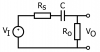
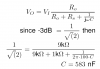
The answer to the exercise may be incorrect, since I get the wrong results every time I do the calculations. It's a simple circuit, and I need the capacitor value, so the output is -3dB at 100Hz.

I get the answer 583 nF, but the answer should be 160 nF

Can someone explain where the calculations goes wrong?
 

Attachments

  • divider.png
    divider.png
    17.7 KB · Views: 852
  • divider-eq.PNG
    divider-eq.PNG
    35.8 KB · Views: 644
Last edited:
The 160nF answer is correct.

There should be a "j" in front of the capacitive reactance term. You must use complex arithmetic.

Since above the cutoff frequency, the gain is -1db, at the cutoff frequency the network should be down to -4db (three on top of the one to start).
 

Attachments

  • Draft2.gif
    Draft2.gif
    58 KB · Views: 464
Last edited:
A 'j' will give me an imaginary capacitance result

The result of the equation must then be -4dB = 0.636
 

Attachments

  • divider-eq2.PNG
    divider-eq2.PNG
    15.3 KB · Views: 363
Last edited:
A 'j' will give me an imaginary capacitance result...

Yes, so what is your point?

You have to use phasors (complex arithmetic) to account for both the phase and magnitude to solve the problem. I was lazy, and didn't do the complex arithmetic. However, I showed you that the answer given with the exercise is correct.
 
Last edited:
MikeMl

You cheated using the computer simulation program. You get zero for not showing your work. :)
 
MikeMl

You cheated using the computer simulation program. You get zero for not showing your work. :)
We are here to show how to do the work, not do the work.
 
I mean, that when solving the equation, the result for C is on the form C=j*'number', which is false
Do you know how to do complex calculations? You convert the rectangular function on the bottom to polar form, do the division, and then convert the result back to rectangular.

Show us your work.
 
Yes, it was just the English term "complex arithmetic" (not my language), that confused be shortly. The result to the equation should have been 0.636 + angle. That's why the result was false.

Thanks for the help :D
 
I just remembered a short cut. The 3db down frequency of this high pass filter occurs when the magnitude of the capacitive reactance equals the loop resistance, i.e. |1/(2ΠfC)| = 1k + 9K

C = 1/(2Πf*(1k+9k) = 1/6.28318E6 = 159.1549E-9 = 159.1nF
 
Status
Not open for further replies.

Latest threads

New Articles From Microcontroller Tips

Back
Top