Continue to Site

Welcome to our site!

Electro Tech is an online community (with over 170,000 members) who enjoy talking about and building electronic circuits, projects and gadgets. To participate you need to register. Registration is free. Click here to register now.

  • Welcome to our site! Electro Tech is an online community (with over 170,000 members) who enjoy talking about and building electronic circuits, projects and gadgets. To participate you need to register. Registration is free. Click here to register now.

voltage divider bias combination

Status
Not open for further replies.
So just to continue, the value of the capacitor connected to the emitter does not matter again very much as all it needs to do is allow signal across the 'space' inhabited by the resistor so that the AC voltage developed has a larger range of amplitude. Yes? If that sounds dummy, I am not clear on this exactly, please let me know.
 
So just to continue, the value of the capacitor connected to the emitter does not matter again very much as all it needs to do is allow signal across the 'space' inhabited by the resistor so that the AC voltage developed has a larger range of amplitude. Yes? If that sounds dummy, I am not clear on this exactly, please let me know.

None of that really makes any sense?.

Essentially the capacitor simply 'shorts out' the resistor - making it as if it wasn't there.

Circuits generally have both DC and AC 'paths', in this case the capacitor means the resistor is 'there' in the DC path but isn't 'there' in the AC path. Likewise, with coupling capacitors, they are only there in the AC path, and effectively don't exist in the DC path.
Thanks, you have made that clear. AC voltage will transit the capacitor but not the resistor. DC voltage will transit the resistor but not the capacitor.
If the capacitor was removed, would this force the AC signal across the resistor and reduce the voltages at the peaks and troughs which would reduce the AC voltage at the collector pin? If the answer is yes, the capacitor in parallel with the resistor at the emitter pin must have something to do with increasing the output signal or at least help to keep the voltage to its maximum value.
 
The resistor in the emitter adds negative feedback, this reduces gain, but improves linearity and quality - bypassing it with a capacitor leaves the DC negative feedback (a good thing to have) but removes the AC negative feedback, thus increasing the AC gain.

Bear in mind the gain of a transistor (Hfe) varies massively, and if you check datasheets could easily be somewhere between 100 and 400 (or more) - the DC negative feedback compensates for this (to some degree) which means you don't have to individually select resistor values for every single transistor you fit in the same circuit.

Historically it was relatively common for resistor values to be 'selected on test' during manufacture of old electronic equipment.
 
negative feedback
This phrase 'negative feedback' appears a lot in the above posts and is used to refer to a component such as a resistor doing something to reduce the gain. I struggle to understand why the 'feedback' is there. What seems more obvious to me is that the resistor will introduce a voltage drop to it's segment of a circuit and this will mean there is less voltage available to other components on that line of components. When I think of 'feedback' I imagine some flow of electrons is connected back to a previous stage of the circuit. So, how does the phrase 'negative feedback' fit with that?
 
When I think of 'feedback' I imagine some flow of electrons is connected back to a previous stage of the circuit. So, how does the phrase 'negative feedback' fit with that?

I would suggest you don't ever think about 'electron flow' (or conventional current flow), it doesn't really help you to understand circuits, and it just causes confusion. I find it's simpler to just consider 'current flow', I don't care if it's negative or positive, I just consider it going from the top of the circuit to the bottom.

Anyway, the negative feedback is from collector to emitter, and essentially works like this:

The collector current is 'near enough' the same as the emitter current (ignoring the extra tiny base current in the emitter).

So if the collector resistor is 2000 ohms, the emitter resistor is 1000 ohms, and the current is 1mA, the voltage drop across the emitter resistor is 1V and across the collector resistor is 2V - so a gain of 2. To calculate it - 2000/1000=2. Simple ohms law.

If you drop the emitter resistor to 100 ohms, with the same 1mA, you now have only 0.1V across the emitter resistor, so a gain of 20 (calculated as 2000/100=20).

Make it 10 ohm, a gain of 200 (2000/10=200).

This is all DC and AC gain, but by placing a capacitor across the emitter resistor you can increase the AC gain (as you're lowering the AC emitter 'resistance'), while keeping the DC gain the same.

So back to the first example, 2000 and 1000 ohms, gain of 2 - now put a capacitor across the emitter, this essentially 'shorts' the emitter resistor out for AC, giving a gain of 2000/0=infinity. Obviously this doesn't happen, as it's not zero ohms, and the transistor only has a certain amount of gain - but by doing so you get the maximum gain possible from the transistor, as there's zero negative feedback.

On the 'bad side', zero negative feedback only means the lowest quality possible, and the stage isn't terribly linear - but it's all swings and roundabouts.

By applying 'reasonable' amounts of negative feedback you get better quality, and a MUCH more reproducible circuit - which is why it's commonly done that way.
 
the stage isn't terribly linear
Okay, I take it that some negative feedback is needed for quality - not that I can see why the work feedback is in that phrase. Negative makes sense to me but 'feedback' seems unnecessary.
Now we come to another word that appears in lots of explanations about transistor bias and that is 'linear'. I hear this word many times at the amateur radio club but can't always stop people to get them to explain what it means. What does this word linear explain and how does zero negative feedback affect linearity?
 
Okay, I take it that some negative feedback is needed for quality - not that I can see why the work feedback is in that phrase. Negative makes sense to me but 'feedback' seems unnecessary.

It's the word 'feedback' which is most important - it can be either negative (reducing gain), or positive (increasing gain - used to make oscillators).

Now we come to another word that appears in lots of explanations about transistor bias and that is 'linear'. I hear this word many times at the amateur radio club but can't always stop people to get them to explain what it means. What does this word linear explain and how does zero negative feedback affect linearity?

A Linear is something 'different' in amateur radio (or CB) circles, and usually refers to a big power amplifier, connected between the transmitter and aerial.

It's called a 'linear' because it will amplify and pass through any kind of RF transmission (in a linear fashion) - standard 'power amplifiers' for transmitters were usually class C, so were mostly for morse code where it didn't matter, and were nothing like linear.

Basically a transistor (or a valve for that matter) isn't a linear device, and the application of negative feedback is what makes it become much more so - non-linearity is one major cause of distortion, and negative feedback makes amplifiers 'usable'.
 
not that I can see why the work feedback is in that phrase.
Very simply, "feedback" takes some of the output of an amplifier and "feeds it back" into the input, hence the expression "feedback".

There are two types of feedback, negative feedback, and positive feedback.

With negative feedback, the signal which is fed back is (usually) 180 degrees out of phase with the original input signal.
This has the effect of reducing the amplitude of the resulting output signal, hence the gain of the amplifier is reduced.
This results in improved linearity of the amplifier as already discussed.

With positive feedback, the signal which is fed back is (usually) 0 degrees out of phase with the original input signal, ie it is in phase with the input signal.
This has the effect of increasing the amplitude of the resulting output signal, hence the gain of the amplifier is increased.
If there is enough positive feed back, the output of the amplifier will keep on increasing until the output signal is as big as it can be with the supply voltage available to the amplifier.
If we are trying to make an amplifier this is a bad thing, as we have just made an oscillator.
If however we were trying to make an oscillator, we have success.
All oscillators use positive feedback.

. I hear this word many times at the amateur radio club but can't always stop people to get them to explain what it means. What does this word linear explain
The word "linear" in this context is a contraction of "linear amplifier".

In a radio transmitter, many of the amplifiers do not have to be linear, depending on the type of the transmitter.

Lets say we have a transmitter with 10 Watts output, and we need 100 Watts out.
We can add an external amplifier which has a gain of 10.

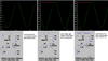
If we test this external amplifier, by putting various amount of power to the input, and measuring the output and get results like this:

Input (W) 1 2 3 4 5 6 7 8 9 10
Output(W) 10 20 30 40 50 60 70 80 90 100
And plot a graph:
1596314505501.png

we have a linear amplifier.

But, if we get results like this:
Input (W) 1 2 3 4 5 6 7 8 9 10
Output(W) 20 40 60 70 77 82 86 91 95 100
And plot a graph:
1596314753433.png

This is a non-linear amplifier.

If our transmitter which is feeding this amplifier is emitting an FM signal, we can use either of these amplifier without any distortion to the transmitted signal.
An FM signal has a constant amplitude.

But, if our transmitter is emitting an SSB signal, we must use the linear amplifier.
The non-linear amplifier will severely distort the SSB signal, it will sound horrible, and it will generate a wide range of intermodulation products which will cause "splatter" on adjacent frequencies.
We will not be very popular with our RF neighbours.


can't always stop people to get them to explain
Well, you can explain it to them now! :)

JimB
 
Last edited:
With negative feedback, the signal which is fed back is (usually) 180 degrees out of phase with the original input signal.
This has the effect of reducing the amplitude of the resulting output signal, hence the gain of the amplifier is reduced.
This results in improved linearity of the amplifier as already discussed.
Question number 1: Why does negative feedback reduce the amplitude of the resulting signal?
Question number 2: How does some negative feedback improve linearity?
 
Question number 1: Why does negative feedback reduce the amplitude of the resulting signal?

Because it lowers the gain - and gives an accurate and easily calculated gain setting.

Question number 2: How does some negative feedback improve linearity?

As the gain is now set by the feedback network, rather than the variability of the device itself, it removes non-linearity of the device.

Or to look at it another way, you're sending back (feeding back) an error signal to correct the defects.
 
Because it lowers the gain - and gives an accurate and easily calculated gain setting.
When I look back up this post, I can see it now. The gain is calculated by dividing collector at voltage by voltage at emitter. When emitter voltage increases then the ratio of collector voltage to emitter voltage will reduce and so the gain reduces. That's something I learned on this post. Sorry, should have seen that one.
 
As the gain is now set by the feedback network, rather than the variability of the device itself, it removes non-linearity of the device
With this one, my thinking is the H network of resistors around the device establishes a linear gain slope in the active region of the transistor.
 
With this one, my thinking is the H network of resistors around the device establishes a linear gain slope in the active region of the transistor.

You try and bias it in the 'most linear' region, but it's still not 'linear' - the negative feedback greatly improves that performance, and accurately sets the gain.
 
You try and bias it in the 'most linear' region, but it's still not 'linear' - the negative feedback greatly improves that performance, and accurately sets the gain.
To return to the circuit I posted at the beginning of this post of an RF transistor amplifier, the collector resistor has a value of 1 k ohms. The emitter has a potentiometer which is 500 ohms, but when the radio works best this pot is set at 20 ohms. If we assume a collector current of 2 mA and agree that the emitter current is the same (2 mA), then the voltage drop across the collector resistor would be 2 volts and the voltage drop across the emitter resistor would be 0.04 volts. To find the gain for this circuit we could divide the 2 by 0.04. This would give a gain of 50.

Does that all follow, and would that be the actual gain that I would achieve in this circuit?
 
Last edited:
And what if I was to reduce the emitter resistor to say 10 ohms? Would that double the voltage gain to 100?
 
Last edited:
Lets say we have a transmitter with 10 Watts output, and we need 100 Watts out.
What I am very greatly interested in is how to amplify microwatts or nanowatts of incoming RF in my crystal radio. I have a tuning circuit set up to deliver roughly 1000 kHz to my amplifier stage. I have a 9 volt battery and I want to use a 2N3904 NPN transistor. The circuit is drawn on the first posting way above but can be seen here.
I am new to forums and their conventions. Should I start a new posting for this topic?

xtalrfamp.gif
 
And what if I was to reduce the emitter resistor to say 10 ohms? Would that double the voltage gain to 100?

In theory - but regeneration is actually positive feedback - like negative feedback, but used to increase the gain. If you increase it too far the circuit will oscillate, but if you increase it 'just' before oscillation starts you get the maximum possible gain from the circuit - also the lowest possible quality of course.

But it's not a crystal radio anyway, as it has an RF amplifier stage, followed by a detector stage.
 
The gain will not be 100, 50 or 100 because the transistor has a resistance at its emitter when it was made. Its resistance is 0.026/Ie which is 13 ohms at 2mA.
So the gain with your 20 ohms emitter resistor is about 1k/(20+13)= 30.3, with your 10 ohms the gain would be anout 1k/(10+13)= 43.5.
This is when the transistor circuit has no load because a load reduces the output level.

I simulated the gain at 1kHz. The gain will be less at radio frequencies.
 

Attachments

  • transistor AC gain.png
    transistor AC gain.png
    40.6 KB · Views: 149
Status
Not open for further replies.

New Articles From Microcontroller Tips

Back
Top