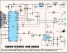
Voice recording chip
Hi Stuart,
I was just going to adivise opening your PC to look for the connectors. They are always used for the Floppy, HDD and ROM connectors. They are commonly called box header (since they are boxed). In my circuit I just the 16pin R/A version for a lower profile.
Changing from Mic to auxiallary input shouldn't be a problem. Just omit the Mic and replace with a shielded cable to your device for recordings. All pins on the box header are occupied and remaking the entire layouts for both, would ruin the work I've done so far. (All traces are routed manually.)
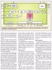
I'm using Eagle version 4.16 as a schematic and layout editor. You can download the latest version 5.0 at Cadsoft.com free. The size restriction of Eagle light PCBs (normally 3.5X3.5inches) does not apply to ready made circuits. (programmer error
")
) The boards are smaller anyway (3.35X2.1inches)
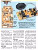
The second board is finished and contains all controls and necessary LEDs. I doubt a bit you'll get the same switches I used for each input/output channel. They must be double pole and leave the option to connect external switches for playback. The blayback lines are at the buttom using screw head terminals. You must connect good ground connection to the car chassis.
All switching from the car to the device is made by grounding the appropriate input pin of the HK828. Besides the eight switches I added a rewind button, which you will need in case of a false recording.
As I already mentioned: Feel free to ask me for the switches if you can't get them at your local electronics shop. I'll send you enough to mess up some of them while soldering.
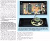
I also added the amplifier circuit directly taken of the Spaceship Enterprise door sounder schematic. If you don't need it just omit the parts around the TDA1905 and the chip itself. In that case use the SP+ labelled solder pad on the board to connect the speaker. You can also omit the three additional jumps on the main board which were necessary to connect the AF-amplifier to the car battery voltage via the 16 pin box header.
The switch board couldn't be made single sided. (Too many twists in the traces because of the switches).
Both boards have exactly the same size and the ribbon cable connector has the same position for a straight ribbon cable to connect both boards. That way they can be sandwich mounted with the switch board on top.
Have a look. Thorough instructions to follow if you have decided to build the circuit.
Regards
Hans