Continue to Site

Welcome to our site!

Electro Tech is an online community (with over 170,000 members) who enjoy talking about and building electronic circuits, projects and gadgets. To participate you need to register. Registration is free. Click here to register now.

  • Welcome to our site! Electro Tech is an online community (with over 170,000 members) who enjoy talking about and building electronic circuits, projects and gadgets. To participate you need to register. Registration is free. Click here to register now.

Visual Analyser

Status
Not open for further replies.

epilot

Member
hi friends,

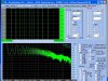
i have found a very good "oscilloscope" called Visual Analyser or VA at:
https://www.sillanumsoft.com/

it is a dual scope with Spectrum Analyser, Frequency meter, Volt meter, Filtering etc.

since today i started to read a book about scopes,then i am not expert with adjustment for now.

i connected about 2M of wire to my sound card and and the end of wire was directly connected to an adaptor(AC transformer), it was a 220V to 7.5 X 2
my idea was to see sine wave of mains but what i saw was a square wave!(see the pic),

can someone say me what is the problem please?
 

Attachments

  • untitled_146.jpg
    untitled_146.jpg
    120.9 KB · Views: 926
epilot said:
hi friends,


i connected about 2M of wire to my sound card and and the end of wire was directly connected to an adaptor(AC transformer), it was a 220V to 7.5 X 2
my idea was to see sine wave of mains but what i saw was a square wave!(see the pic),

can someone say me what is the problem please?

You are overdriving the sound card. From memory, I believe the input voltage to the sound card must not exceed 2 Volt peak to peak.

So I suggest you connect a potentiometer to reduce the voltage.
 
ljcox said:
You are overdriving the sound card. From memory, I believe the input voltage to the sound card must not exceed 2 Volt peak to peak.

So I suggest you connect a potentiometer to reduce the voltage.

Yes, in fact you'll be lucky if you haven't already damaged it. The first clue that you are overdriving the sound card should be that you can't actually see the peaks of the signal on the display... that means they are going "off the screen" so to speak. Whenever your signal is going off the screen like that, you know you're not seeing an accurate representation of it.
 
evandude said:
ljcox said:
You are overdriving the sound card. From memory, I believe the input voltage to the sound card must not exceed 2 Volt peak to peak.

So I suggest you connect a potentiometer to reduce the voltage.

Yes, in fact you'll be lucky if you haven't already damaged it. The first clue that you are overdriving the sound card should be that you can't actually see the peaks of the signal on the display... that means they are going "off the screen" so to speak. Whenever your signal is going off the screen like that, you know you're not seeing an accurate representation of it.

the wire went to MIC socket and there might be a capacitor so i dont think 15V makes any damege :)

really i dont know,i have read about 4 page about it and there was no thing about input and voltage limitation!
the software has a voltmeter too so i am suspect that we can give only 2V MAX to iput!

i had a test with a 47K resistor for input in series but the result was the same,

who know how many Voltage(MAX) we can give to input of a REAL scope?
 
A capacitor wouldn't protect it from high input voltages. it's possible that the sound card has protection diodes, however those can still be overloaded if you don't limit the input current. For that reason, you should DEFINITELY use a series resistor on the input, such as the 47K you used.

As far as I know, sound cards always have an AC-coupled input, so you cannot use them for measuring DC signals, thus they would be no good for a voltmeter, unless you mean an AC voltmeter.

Using a 47k series resistor alone would not significantly affect the voltage of the input, you would have to use a resistor divider to drop the input voltage to a range that the sound card could read.

A "real" oscilloscope can often handle voltages of over 100V, and often over 1000V if an attenuated probe is used. Real oscilloscopes also aren't AC-coupled (well, unless you enable it) so they can directly measure DC voltages. And, of course, an oscilloscope can go to MUCH higher frequencies than a sound card, even low-end scopes can handle 10's of MHz. Also, you should know that a sound card is NOT going to provide distortion-free measurements of your signal. I'm not saying it's totally worthless; those sound-card-oscilloscope programs are definitely interesting because they let you experiment with some limited signals, and are great for demonstration and experimentation for people without any real oscilloscope experience, however they are not all that useful when it comes to actual electronics testing, because they can only handle a rather narrow set of signals.

Face it, soundcards are NOT built to be oscilloscopes.
 
epilot said:
really i dont know,i have read about 4 page about it and there was no thing about input and voltage limitation!
the software has a voltmeter too so i am suspect that we can give only 2V MAX to iput!

i had a test with a 47K resistor for input in series but the result was the same,
As I and evandude wrote earlier, the sound card is being overloaded, that is why you are not seeing the peaks of the sinewave signal.

You need to attenuate the signal. If it is 15 Volt AC, then I suggest a series 47 k and a shunt 1 k to gnd. That will attenuate the signal by about 48:1, so a 15 Volt RMS signal will be reduced to about 1 Volt peak to peak.

However, note that a 15 Volt AC plug pack may output 20 Volt RMS or more with no load since there is no regulation.
 
evandude said:
A capacitor wouldn't protect it from high input voltages. it's possible that the sound card has protection diodes, however those can still be overloaded if you don't limit the input current. For that reason, you should DEFINITELY use a series resistor on the input, such as the 47K you used.

As far as I know, sound cards always have an AC-coupled input, so you cannot use them for measuring DC signals, thus they would be no good for a voltmeter, unless you mean an AC voltmeter.

Using a 47k series resistor alone would not significantly affect the voltage of the input, you would have to use a resistor divider to drop the input voltage to a range that the sound card could read.

A "real" oscilloscope can often handle voltages of over 100V, and often over 1000V if an attenuated probe is used. Real oscilloscopes also aren't AC-coupled (well, unless you enable it) so they can directly measure DC voltages. And, of course, an oscilloscope can go to MUCH higher frequencies than a sound card, even low-end scopes can handle 10's of MHz. Also, you should know that a sound card is NOT going to provide distortion-free measurements of your signal. I'm not saying it's totally worthless; those sound-card-oscilloscope programs are definitely interesting because they let you experiment with some limited signals, and are great for demonstration and experimentation for people without any real oscilloscope experience, however they are not all that useful when it comes to actual electronics testing, because they can only handle a rather narrow set of signals.

Face it, soundcards are NOT built to be oscilloscopes.

oh, i was Disappointed after redaing these paragraphs,

really i would like to get a real scope but recently i lost a lot of my money buying a 5A regulator voltage adaptor, i bought it about 100$
and a good scope here is at least 500$ so i thought perhaps a software like that VA could be a good thing to see wave shape and specially frequency,

by the way i used from a 1Mohm resistor and could get a sine wave, thanks for directing :)
 
Well, for basic experimenting with signals the sound card thing isn't a bad idea. And, if you want to build something like an audio amplifier or something, it might be pretty usable. It's just that for any signal outside of the normal audio range (20Hz to 20KHz), or anything involving DC, it's not going to be very useful. Also, due to the frequency response of the sound card, signals like square and triangle waves at the higher end of the frequency are probably going to be pretty distorted, looking more like sine waves.
 
ljcox said:
epilot said:
really i dont know,i have read about 4 page about it and there was no thing about input and voltage limitation!
the software has a voltmeter too so i am suspect that we can give only 2V MAX to iput!

i had a test with a 47K resistor for input in series but the result was the same,
As I and evandude wrote earlier, the sound card is being overloaded, that is why you are not seeing the peaks of the sinewave signal.

You need to attenuate the signal. If it is 15 Volt AC, then I suggest a series 47 k and a shunt 1 k to gnd. That will attenuate the signal by about 48:1, so a 15 Volt RMS signal will be reduced to about 1 Volt peak to peak.

However, note that a 15 Volt AC plug pack may output 20 Volt RMS or more with no load since there is no regulation.

yes i used from a 1Mohm resistor and could get a sine wave,
i have heard Sony makes a kind of scopes based on PC that use from a special hadrware and thought they should be inexpensive but someone said me that they are more than 500$ too :shock: :roll:

by the way i have sent you an PM

i have sent an PM to you
 
The microphone input of a sound card is desisgned to power an electret microphone with a few volts DC at about 500uA. It is designed to receive a signal from the microphone of only 10mV and maybe 100mV max.

When you connected a 1M resistor in series with the input to create a voltage divider with the sound card's internal input impedance then the frequency response is messed due to the capacitance of the input which creates a lowpass filter.
Therefore it is capacitor-coupled and can't be used for DC, and its frequency response is messed and can't be used for AC.
 
Yes, as audioguru says the 1 meg resistor isn't a good solution, the voltage divider mentioned earlier is a better choice at least.

Also, if you can, try using a Line-in jack instead of a microphone jack, it is designed for a much wider range of input. Although, on many sound cards the microphone and line inputs share the same jack and you have to choose which one to use through software.
 
Yep defently way to much voltage in the pour soundcard.

The mic output aculy sends a bit of curent because you have mic that dosent make any voltage (well dinamics do but very litle)Even an resistive load will drive the mic input.The line in expects voltage.Thats why an mic wont work on it.

yea use an pot and resistor to make an voltage divider in case you will need to see singlas above 2V in the future.
 
Status
Not open for further replies.

New Articles From Microcontroller Tips

Back
Top