i connected the camera directly using a cord to the tv. it can receive PAL camera signal.
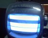
i changed the bias on the transistor base. but,no use.i am now getting a plain white screen,when tuned to the tx signal.anybody know what it means?
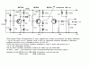
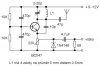
actually,i built a circuit. but it is a simple one transistor circuit.it worked for me.but the quality is poor. please take a look at it. any chance of modifying the present circuit to work like this?i chose the second circuit,because it has different stages and quality and range will be more.but,its not working.please help
In the U.K. the video is modulated such that white corresponds to maximum carrier amplitude (Positive modulation).
This takes
**broken link removed**
If the screen is all white when you tune to the transmitter, then the carrier is there, most likely (but not necessarily) the sync pulses are being transmitted, but there is no video modulation -that is to say that the darker parts of the video signal (if there are darker parts) is not affecting the carrier amplitude.
An alternative explanation, though less likely, is that the camera is starting at a white card or into a light.
This takes us back to adjusting the bias and the video level on the video modulation transistor.
The differences between the transmitter that works and the complicated circuit is that the complicated circuit has a buffered RF oscillator a buffer for the video signal.
I think the main advantage of the more complicated circuit (without deep analysis) is that the output power is likely to be a little higher and have a less frequency modulation in the signal. The video buffer transistor (which I referred to in previous posts at the video modulation transistor) adds a little temperature stability to the modulation, but perhaps more importantly, may (if my guess is right) diode clamp the blacks so that the black level doesn't sift around as scene content changes.
I am reluctant to try a design by "remote control" over the web and not having access to PAL equipment, I am not able to take on this as a design task.
Most likely, your best course is to assure that you have built the circuit according to the schematic and then to continue to experiment with the bias and video level adjustment. Alternatively, look for another design on the web.
If you can get your hands on an oscilloscope, it will probably help you a lot.
Whether you can get a scope or not, being familiar with the TV signal modulation waveforms will at least let you visualize how changes to the circuit can affect the picture.
Have a look at this site (from which I lifted the image above).
**broken link removed**