Continue to Site

Welcome to our site!

Electro Tech is an online community (with over 170,000 members) who enjoy talking about and building electronic circuits, projects and gadgets. To participate you need to register. Registration is free. Click here to register now.

  • Welcome to our site! Electro Tech is an online community (with over 170,000 members) who enjoy talking about and building electronic circuits, projects and gadgets. To participate you need to register. Registration is free. Click here to register now.

VETRA on it's way!

Status
Not open for further replies.

Krumlink

New Member
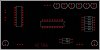
3v0 and I were working on IR detection, and after some brainstorming, we came up with creating a IR robot, That could explore a room autonomously, and would be able to be reprogrammed through a 2x5 ICSP port on the side of it. I am currently working on the PCB still, but it will be done very quickly.

18F1320 Brain
2 IR Emitters
2 IR Recievers TBD what they exactly are
SN754410 Motor Driver

The hardware would be exactly the same through out the design, but it will come with a ICSP header in case you want to change a part of the code.

More to come soon!!

EDIT: The pic is a VERY early stage in the Board, but the IC's and LED's are likely to stay there.
 

Attachments

  • vetra.JPG
    vetra.JPG
    40.7 KB · Views: 311
Did you select the motor/gearbox for your robot project ? If you want to use the classical 2 motor configuration I'd say Bill is correct that a PIC with 2 PWM would be a better choice. I planned to play with robotics as well, ordered some Tamyia gearboxes and wheels from www.pololu.com and also their robot chassis - it is really quite cheap, but I did not have time to continue with this project ...
It would be interesting to hear more about your robot project :)

Petr
 
Krumlink said:
2 IR Emitters
2 IR Recievers TBD what they exactly are

I'll try one more time?, check my website I posted a link to previously for you, you only need one receiver and two emitters - it's not something I designed and wrote, I just used the original designers product.
 
Nigel Goodwin said:
I'll try one more time?, check my website I posted a link to previously for you, you only need one receiver and two emitters - it's not something I designed and wrote, I just used the original designers product.

Yes, I looked at the site, but for simplicity we are going to use 2 sensors and 2 emitters, each easily representing Left and Right side. Maybe you mean 2 sensors and 1 emitter, but the emitter better be pretty bright!

Besides, It will as i already said represent the left and right sides better.

blueroomelectronics said:
May I humbly suggest a 28pin PIC (the 18F2525) as it has 2 PWM (motor channels), just connect it like the Mongoose schematic.

Meh, DENIED :) Only because the 18F1320/1330 is working good for us, but maybe a future robot?

petrv said:
Did you select the motor/gearbox for your robot project ? If you want to use the classical 2 motor configuration I'd say Bill is correct that a PIC with 2 PWM would be a better choice. I planned to play with robotics as well, ordered some Tamyia gearboxes and wheels from www.pololu.com and also their robot chassis - it is really quite cheap, but I did not have time to continue with this project ...
It would be interesting to hear more about your robot project :)

Petr

Yes, I was going to use bills tamyia gearbox in configuration C. :)
 
Krumlink said:
Yes, I looked at the site, but for simplicity we are going to use 2 sensors and 2 emitters, each easily representing Left and Right side. Maybe you mean 2 sensors and 1 emitter, but the emitter better be pretty bright!

No, one sensor and two emitters, it's all that's needed - brightness of the emitters can be altered to increase the range, but it's basically only short range anyway, and highly dependent on the IR reflection properties of the object.

Besides, It will as i already said represent the left and right sides better.

No it wouldn't, but feel free to use two receivers if you like :)
 
Oh i get at what you mean now, just in the software tell when it left side is on and right side is on?

That would not work very well (cyclops robot) because, this robot wants to tell if it is going to hit left side or right side at the same time. It would only be a limiting factor.

PCB is coming along good :D
 
Krumlink said:
Oh i get at what you mean now, just in the software tell when it left side is on and right side is on?

That would not work very well (cyclops robot) because, this robot wants to tell if it is going to hit left side or right side at the same time. It would only be a limiting factor.

Not at all, the 8 pin PIC outputs signals for left and right, both together mean an object directly in front - as with anything electronic it's far, far faster than the mechanics involved in the robot - it works extremely well, and just as good (if not better) than a double sensor solution.

By using a separate 8 pin PIC all you need to do is check the L and R pins from it, I even added LED's on the output so you can see what's happening.
 
We need to build and get your walter class robot working. It will teach you things that will make VERTA better. Walter is also a good test bed for trying new things.

You have everything you need to build a walter including the PCBs.

The software to drive it is easy and we can walk through it this weekend. Once the robot moves we can work on the wall detection.

Bolt the drive unit to the bottom with the motors sticking out the back a bit. It is best to select a location for the holes/screws so they are between card slots. The same goes for the caster. Keep the screws short. The blue tape is to keep lint and pet hair out of the gears. You can get a small pack of 4-40 screws and a pack of nuts at radio shack. Some crimpers have holes to shorten screws.

Each motor should have a red and a black wire that will go to the h-bridge. Drill out the short standoffs in the back above the motor and run the motor wires through them into the box. Put the caps on the motors when you add the wires and make sure the motors go into the clips with the wires and caps in place.

Bolt the battery boxes to each side of the box above the rear wheels. If you move them too far ahead there will be too much weight on the caster. Drill a small behind each battery holder and run the wires into the body.

Use a small rectangle of perf board with a hole in the center for a small toggle switch. Add a 1A resettable fuse if you have one. Wire a battery red wire to one side of the switch, the other side of the switch to the fuse and the fuse to the black wire from the other battery holder. Drill a hole in the center of the back body wall and slip the switch through, add lock washer and nut.

You now have a black and a red battery wire. One from each holder. These will power the h-bridge. You also need to power the CPU board so a 4" bit of wire to each and solder them. In this case the twisted together soldered ends will go into the h-bridge screw terminals.

Tin the other ends of the wires you just added.
Twist each set of motor wires by chucking them into a cordless drill. We will cut them to length and tin them latter.

**broken link removed**

Drive and switch in place. The batteries and caster still need to be added.

The further ahead you place the wheels the easier it will be to do wheelies. Test balance prior to drilling if you want to do this.

I can provide more pics if you want/need them.
 
Last edited:
Building Walter and VETRA are 2 completely seprate things, althought both of them seem like they are the same project. VETRA is seprate from our C learning. VETRA is more like a personal project that uses what I learn from C. As for actually learning new C content, that is where Walter is coming in. I learn with Walter and apply it with VETRA. :D

This is what I always do, I learn with one tool and use what i learn with another tool, a good example of this is worksheets/assignments you get in school. :)

Walter will not take long to assemble, and I will use 2.4V with the Motors, since my Gearbox likes that voltage without squeeling too much. I will operate the circuity off a 9V battery (Alkaline to take into affect voltage) or a 8 pack of AAA/AA cells.

Not at all, the 8 pin PIC outputs signals for left and right, both together mean an object directly in front - as with anything electronic it's far, far faster than the mechanics involved in the robot - it works extremely well, and just as good (if not better) than a double sensor solution.

By using a separate 8 pin PIC all you need to do is check the L and R pins from it, I even added LED's on the output so you can see what's happening.

1. I don't have any 8 Pin PIC's nor do I want to deviate from the 18F series (You used a PIC12F right).
2. A 1 Sensor 2 LED design does not make sense, unless you sent a signal through the LED's, even then it does not make sense.
3. For ease of programming, a 2 sensor design would be superior, because all you have to do is when it detects an input it reverses, when it doesnt drive straight.
4. A "cyclops" robot has a disadvantage over a 2 eye robot.
5. From your description how would the sensor be able to tell what side from what? remember that I am learning C, and I am not going to use Assembly in this robot, and It will just make it more complex.
 
Last edited:
Krumlink said:
1. I don't have any 8 Pin PIC's nor do I want to deviate from the 18F series (You used a PIC12F right).

It used a 12C508, it long pre-dated the 12F series - a 12F would make more sense though now.

2. A 1 Sensor 2 LED design does not make sense, unless you sent a signal through the LED's, even then it does not make sense.

Makes perfect sense, and is dead easy to use - you simply send 38KHz pulses out one LED and check for a reflection on the receiver, then send 38KHz pulses out of the other LED and check for a reflection on the receiver.

Exactly the same as you do with two receivers, except you only need one.

3. For ease of programming, a 2 sensor design would be superior, because all you have to do is when it detects an input it reverses, when it doesnt drive straight.

Exactly as a single sensor does, you check for both left and right objects and reverse the appropriate motor(s) - BTW you can't just reverse if you find an object ahead, you need to turn as well - my original code turned either direction at random.

4. A "cyclops" robot has a disadvantage over a 2 eye robot.

It's not a 'cyclops' robot, it detects from both left and right independently, but just doesn't waste an extra IR receiver - no disadvantage at all.

5. From your description how would the sensor be able to tell what side from what? remember that I am learning C, and I am not going to use Assembly in this robot, and It will just make it more complex.

Explained above.

It makes it incredibly easier for you - just use an 8 pin PIC like in my project - this connects via two pins to your 18F PIC, one for left, and one for right - all your C program needs to do is check if the pins are high or low.

Like I said previously, I didn't originally write this - but it's fairly complex in operation, because it uses a voting system to reduce false readings - certainly I found it extremely effective.
 
its not looking straight ahead! Both sensors are looking at a 45 degree angle, that way if left detector senses a wall it backs up the opposite side of the H bridge, but if right side does not detect it goes straight, making it turn.

With a 1 sensor design it can only look straight ahead without favoring one side.
 
Krumlink said:
its not looking straight ahead! Both sensors are looking at a 45 degree angle, that way if left detector senses a wall it backs up the opposite side of the H bridge, but if right side does not detect it goes straight, making it turn.

That's fine for an object either side - but what for an object directly ahead? (like a wall) - if both motors reverse what does it do next?.

With a 1 sensor design it can only look straight ahead without favoring one side.

No, it looks both left any right - IR receivers have a wide acceptance angle - hence why you only need one of them - you position the LEDs for the actual beamwidth you want.
 
I am going to use a 2 sensor design since I have experience with 2 sensors like that. Also because the sensor is actually bulging out of the packaging slightly, it is a very wide angle reciever. I will be able to see in front slightly , and it will most likely be around 30degrees from straight ahead. I could add a switch if I wanted to. if it detects both, it will back up for a few seconds, and advance.

The software is still being wrote to, but the actual hardware will be the same, so we could adapt to what we need.
 
Krumlink said:
I am going to use a 2 sensor design since I have experience with 2 sensors like that. Also because the sensor is actually bulging out of the packaging slightly, it is a very wide angle reciever. I will be able to see in front slightly , and it will most likely be around 30degrees from straight ahead. I could add a switch if I wanted to.

Like I said, feel free to use two, but it offers no advantage whatsoever.

if it detects both, it will back up for a few seconds, and advance.

And what good would that do?, it spots a wall in front, so it reverses - it then goes forward again and hits the same wall - repeat until battery is flat :p

Which is why I said earlier, it needs to turn to avoid the wall if it finds an object directly in front. My first solution was to reverse for a certain time, then always turn the same way (can't remember if it was left or right) - but that was a bit boring and meant it could get stuck. So I altered the routine to make it turn a random direction if it found an object if front - this was far more fun, and makes it behave much more 'alive'.
 
Krumlink said:
Building Walter and VETRA are 2 completely seprate things, althought both of them seem like they are the same project. VETRA is seprate from our C learning. VETRA is more like a personal project that uses what I learn from C. As for actually learning new C content, that is where Walter is coming in. I learn with Walter and apply it with VETRA. :D

This is what I always do, I learn with one tool and use what i learn with another tool, a good example of this is worksheets/assignments you get in school. :)

Walter will not take long to assemble, and I will use 2.4V with the Motors, since my Gearbox likes that voltage without squeeling too much. I will operate the circuity off a 9V battery (Alkaline to take into affect voltage) or a 8 pack of AAA/AA cell.

Power walter with the 2 AA battery holders I provided. It is the same setup
as Bill used on Moongose but the Miss Motor H-Bridge is not nearly as efficent as chip used by mongoose. Wire it as I instructed. You can pick the speed/power you want with PWM.

You doing what you always do can be very frustrating.
 
Status
Not open for further replies.

Latest threads

New Articles From Microcontroller Tips

Back
Top