Hi guys i am very new to all this and want a simple circuit that will replicate the starting lights of a formula 1 race for my sons scalextric. So i have 5 led's and a 1.5V battery. I know how to connect these even with a resistor ! but thats about it. For those of you not aware of the F1 start, I require the lights to come on in sequence at 1 second intervals and stay on until the fifth light is lit when this is lit i then need them to all go out ideally with a random pause between 1 and 3 seconds but if thats too tricky for me then just a standard 1 second interval will be fine. The other thing is that i would like this to be cheap, at the moment my parts cost under 50p I don't want to be buying £20 parts! Also if there is something premade i can just wire into the system that would be great. The other issue i may have is that i don't fully understand circuit diagrams, i'm fine with basic electrics but not electronics !. I you could point me in the right direction for simple explanations that would be great.
Continue to Site

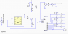
") Just another way to do it.
Just another way to do it.