Continue to Site

Welcome to our site!

Electro Tech is an online community (with over 170,000 members) who enjoy talking about and building electronic circuits, projects and gadgets. To participate you need to register. Registration is free. Click here to register now.

  • Welcome to our site! Electro Tech is an online community (with over 170,000 members) who enjoy talking about and building electronic circuits, projects and gadgets. To participate you need to register. Registration is free. Click here to register now.

Very Basic 7 segment display circuit

Status
Not open for further replies.

jb_604

New Member
Hello guys,

I need help with a very simple circuit that displays one word when it is powered on. My daughter wanted this for her school project and I thought I would try and help her out...but electronics is not my area of expertice at all.

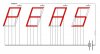
Basically, she just wants to display a simple 4 letter word using 4x 7 segment led's...would someone be kind enough to tell me what I would need in terms of materials, and how I would connect up such a circuit. I already have a 5V power supply, a breadboard, and the led's.

Thanks in advance!
 
Hi.

Does the word need to change at all or will it be fixed? If it is fixed, it is simply a case of connecting up the correct lines up.

7 segment displays have either a common cathode(-ve) or common anode(+ve), so it would be worthwhile knowing that(there are two common pins - be careful not to create a short). Once you have connected the common up, the others will each light up one segment.

Depending on the rating of the power supply you may need current limiting resistors also, but once again it depends on the display you have.

More info here: Interfacing to 7-Segment Displays
 
Hello,

Thanks for the reply. This doesn't need to change at all...it is fixed. That is the problem I have been having in searching online for help. I can only seem to find complex circuits involving microcontrollers, switches, and counters. Would I need anything other than the LED's, resistors, power supply and breadboard?

Thanks again....and for the link. I will read through it to see if i can make sense of it.
 
All you should need are the displays, PSU, and resistors. Each display should have 8 pins. One will either be the common cathode(ground) or common anode(power). Connect the Common pin to either the ground or power. And then connect the pin corresponding to the LED(to either ground or power depending on your version) you want to light through a resistor.

Thats all there is to it :)
 
Seven segment displays are intended to show numbers, not words. Even using them to display hex numbers is tough. For example, the number six gets mistaken for the letter 'b'.
 
Seven segment displays are intended to show numbers, not words. Even using them to display hex numbers is tough. For example, the number six gets mistaken for the letter 'b'.

Yeah...she is aware that some letters might be mistaken for something else...like the letter V will show up as a U.

one last question if you don't mind....this is probably also pretty dumb but how can I control which segment on each LED lights up to display a character? I know the basic concpet of how it works, but not how to implement it in the actual circuit
 
Here is a typical hookup. For segements A & B. For 5V the resistors are typically 220Ω
 

Attachments

  • 7 segment conn.JPG
    7 segment conn.JPG
    18.3 KB · Views: 3,907
Look at the data sheet for the display you are using. It will tell you what the pinout is (what each pin does). Most 7-segment displays have 10 pins: 7 for the digit segments, one for the decimal point, one common (cathode or anode) and one unused (or could be a 2nd common pin).

Then, draw a diagram on a piece of paper so you can work out what segments need to be lit up. Start with one "digit". Wire those segments' pins through resistors to your power supply, connect the common pin to ground (if the display is common cathode, or the + side if common anode), and see what you get. If the right segments light up, you're good. If not, fix your mistakes and try again. Repeat for each additional digit.

To make things simple, use separate single-digit displays rather than a multi-digit display. Most multi-digit displays share the segment pins and have a separate common pin for each digit, meaning you'd have to multiplex the display to display different characters on each digit.


Then,
 
Thanks for all the help guys...I will work on it tonight and see how it goes...I have a much better understanding of what needs to be done.
 
Yeah...she is aware that some letters might be mistaken for something else...like the letter V will show up as a U.

one last question if you don't mind....this is probably also pretty dumb but how can I control which segment on each LED lights up to display a character? I know the basic concpet of how it works, but not how to implement it in the actual circuit

Select your power supply. If its about 5 volts you'll use 220 ohm resistors. Solder a resistor to one of the power leads. Take one of the displays. Attach one power lead to the common lead on the display. Touch the other lead to one of the LED pin outs. A segment should light. If it doesn't reverse the two wires from the power source. As you touch to different pins different segments will light up.

The most simple approach is to use a 220 ohm resistor to attach a lead to each of the segments you want to light up. That hard wires your display.

Use a direct line from the common to the power source and a resistor from the power source to each segment you want to light.
 
Hi,

Ive used a single resistor for this sort of thing before, with no noticeable differences.

Circuit shown is very simple.
The common can be anode or cathode, i think anode is more usual.

With a fixed display, you can take liberties, the centre led can be partly taped or painted over to help with a "G". Units can be moved a half-segment up or down to improve the letters with a tail on lower case. If you are prepared to cut them about, extra bits can be added for some letters.

Best of luck with it.
John :)
 

Attachments

  • PEAS.leds.JPG
    PEAS.leds.JPG
    47.1 KB · Views: 918
Last edited:
Whats the word ?

You're kidding right? A four letter word with "V" in it, that would be important enought to stand alone on a display and be of interest to a girl? Don't take up crosswords. :)

I would parallel the segments and juts pick one resistor for each display. The effort to "hand tune" 4 resistors is much easier than soldering the 15 resistors which is the alternative.
 
This circuit displays Stroop when turned on. It can be changed to any word
 

Attachments

  • StroopCct.gif
    StroopCct.gif
    9.5 KB · Views: 547
Hi Y'all,

Yes. I thought it was that, but i thought i would ask.
To make what i would consider a satisfactory 'V' i would have to physically interfere with one of the seven segment displays. But it could be done neatly.

As to the limiting resistor, i have run many LEDs in parallel before without any being noticeably dimmer than others.
Having them all in parallel and choosing a suitable value, is probably easier than choosing four resistors.

If the original poster comes back, i would like to see a pic of the result.
My guess is a badge with a couple of button batteries.

John :)
 
Status
Not open for further replies.

Latest threads

New Articles From Microcontroller Tips

Back
Top