Continue to Site

Welcome to our site!

Electro Tech is an online community (with over 170,000 members) who enjoy talking about and building electronic circuits, projects and gadgets. To participate you need to register. Registration is free. Click here to register now.

  • Welcome to our site! Electro Tech is an online community (with over 170,000 members) who enjoy talking about and building electronic circuits, projects and gadgets. To participate you need to register. Registration is free. Click here to register now.

Variable Current Source (by electronic switch)

Status
Not open for further replies.

mrfunkyjay

New Member
Hi, I had my schematics design for my final thesis work, in which I need to construct a variable current source, driven by an electronic switch.

On my way to completion, I found it useful to use CD4066B while four switches are sufficient to simply give the four different current source outputs I need.

Is 1 = 1mA
Is 2 = 5.7mA
Is 3 = 10.4mA
Is 4 = 15.2mA

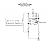
The values above are obtained by simply divide the 1.25V by the amount of four resistors to give such output current. (Refer to LM317 data sheet, the Vref is equal to 1.25V and R1 is denoted as the current adjuster).

There is a schematics below, what my question is:

-The VDD and VSS of CD4066. What amount of voltage do I need to apply at the VSS pin? I don't get it working since I give 0V or GND connection to the VSS while VDD and VC are equal to +5V. Since I am controlling this circuit with microcontroller, so 5V voltage range is convenient to use. Please help, I am really confused. Should I give the VDD = +5V, VSS = -5V and VC equal to LOGIC 1(HIGH) = 5V and LOGIC 0(LOW) = 0V ???

Correct me if I'm wrong...

Best regards,

Kelvin
Indonesia
 
By the way, this is the SCHEMATICS... Thanks!
 

Attachments

  • Variable Current Source - Schematics.pdf
    30.5 KB · Views: 1,081
I see one possible problem. The internal resistance of the 4066 is about 90 ohms, so for accurate current you will have adjust the values of the external resistors. When the control voltage on pins 5,6,12,and 13= pin 14 voltage that particular switch will be on. When the voltage = pin 7 voltage the particular switch is off and represents a high resistance. I think pin 7 can be normally grounded and pin 14 at 5 volts.
 
As k7elp60 stated, the switch resistance is a problem. This can be avoided by using two switches, one to switch the resistors, and one to switch the sense voltage to the Adj pin of the LM317:

1. Move the sense resistors from the output of the switches to the input of the switches (at the output of the LM317).

2. Add another 4066 switch between the LM317 Adj pin and the output of each resistor (junction between the resistor and its select switch.

3. Operate the two switches from the same control signals so that each selects the same resistor.

The above changes will prevent the Adj pin from seeing the resistance of the resistor switches. (The resistance of the switch in series with Adj is not a problem since the Adj current is so small).

Another problem with the circuit: The LM317 requires at least 2 volts to operate, and the voltage across the sense resistor is 1.2V, so from a 5V supply the maximum allowable load voltage would be 5-2-1.2 = 1.8V which makes a very limited constant current source. You need a voltage for the LM317 that's at least 3.2V higher than the maximum required load voltage. The voltage to the switches would then need to increase also.
 
Last edited:
Last not least the minimum current for the LM317T (as contained in the schematic) is 10mA.

Use an LM317L down to 500µA.

Further the switching capability of the HCF4066 is +/-10mA at VDD=15V.

My suggestion: Use BS250 (p-channel) MosFets for switching.

Boncuk
 
Last edited:
Yet another solution: AGD451 (Analog devices).

Four bilateral switches independently switching, R=4Ω, flat=2Ω, different package types, also DIP-16.

Here's the data sheet.

Boncuk
 

Attachments

  • ADG451_452_453.pdf
    404.5 KB · Views: 617
thanks all for your help.. I see it is a problem with the internal resistance of CD4066B while it has quite big 90 Ohm (according to my calculation in the schematics design) internal resistance.

Hence, my objective now is to fix what I have now (the PCB is etched), hopefully with a limited time of my thesis work period I could quickly fix the PCB I made by just changing several components (resistors, etc) instead of adding another few! Only if the problem still there, then I would redesign all my layout. So, I need your advice again here... :)

Regarding @crutschow 's explanation, I would like to ask several questions:

-On the LM317 side:

Let's take an example of determining the R1 for 10mA current source (since it is the minimum output current LM317 can deliver >> Might wanna change to LM317L as Boncuk said). Then the calculation would be:

1.2V : 0.010A = 120 Ohm (Is it correct?)

BUT not to forget the internal resistance of CD4066, so when I assume it to be 90 Ohm then to deliver such 10mA of current, the external resistor in one of four switches output must be substracted by 90 Ohm.

This gives 120 Ohm - 90 Ohm = 30 Ohm >>> nominal resistance value for one of four switches to give 10mA output current source.

When the voltage drop across the RLoad is maximum 5V-2V-1.2V = 1.8V, the maximum resistance the current source can supply is equal to 1.8V : 0.010A = 180 Ohm

FYI: The purpose of having this variable current source is to sense the different voltages of each E12 Resistor in two decades ranging from 1 Ohm - 8.2 Ohm to 10 Ohm - 82 Ohm. This is put at the RLoad terminal of my current source before amplified (the voltage drop across RLoad) with Instrumentation Amplifier as an input to 10bit ADC in uC unit. Since the maximum measured resistor is equal to 82 Ohm, from what I did above, 180 Ohm range is far away from 82 Ohm and it is adequate to supply 5V power to LM317. Even if I supply with 20mA current, the maximum allowable resistor is 1.8V : 0.020A = 90 Ohm, it is still in range!

The problem:
-I am trying to deliver not 10mA ++ but also 1mA, 5mA, 10mA, and 15mA (max) this is used to vary the voltage output of my current source circuit to be gained by the inst.amp (the inst.amp is also variable gain with four switches as CD4066 one) so the output to the ADC is always above 1V (resolution is 5mV, I took 1V because it is 20% of the maximum range 5V, hence increase accuracy).

I believe from what I read above, substituting LM317 to L type might work!

And my thesis title is: An automatic resistor measuring and sorting device using uC by the way...

Guys, I am very thankful if you could read and understand, my english is not very good since I am living in such a non-english-speaking country. I hope I could get some ideas here, thanks!

Correct me if I'm wrong! :) thanks all!

Best regards,

Kelvin
Indonesia
 
Last edited:
Yet another solution: AGD451 (Analog devices).

Four bilateral switches independently switching, R=4Ω, flat=2Ω, different package types, also DIP-16.

Here's the data sheet.

Boncuk

it is interesting, I am checking the availability of that chip in my country, thanks!
 
it is interesting, I am checking the availability of that chip in my country, thanks!

Hi mrfunkyjay,

it's a pleasure to me to meet another German at the Forum. :)

Here's one way to check availability: Order free samples at AD. :D (or pick them up personally at Mittlerer Ring, if they are still there).

One remark concerning the LM317L chip. It is small (TO92 package) and can deliver up to 100mA of current. Its nominal reference voltage is 1.25V (not 100% guaranteed)

To make your measuring device precise (don't forget about the famous german accuracy!) obtain a sample (many shops in Munich, Schillerstraße, e.g. Conrad electronic) and measure the reference voltage at a live object.

Thereafter calculate the resistance values required for different currents and use 25turns worm gear driven trim pots (Y64) for finest and most accurate tuning, even compensating for the 4Ω resistance of the chip I suggested.

E96 row resistors are in the tolerance class of 1%. Your circuit must be below that tolerance to determine the value of the resistor under test.

Regards (Herzlichen Gruß)

Hans
 
Last edited:
Although I am not German, I know what u mean by Schillerstrasse usw. ha!! It reminds me back then 2008 when I had my 6th semester international internship in Munich, Germany.

Regarding the LM317 and its problem in my schematics I choose to test out the CD4066 if it would work with TL084 (my instr.amp), if it is successful then I do not have to be worry about the LM317 - CD4066 pair, just make the current constant by using LM317, then supply the Load Resistor, amplify (if necessary) with instr.amp. I would like to make sure my voltage output to 10bit ADC is higher than 1V, so Voltage Comparator at the end of the circuit series is necessary.

Thanks all for your support, I will try again the CD4066 with simple schematics first, then mix it with my instr.amp to have a variable controlled GAIN. Thanks!!!

Hi mrfunkyjay,

it's a pleasure to me to meet another German at the Forum. :)

Here's one way to check availability: Order free samples at AD. :D (or pick them up personally at Mittlerer Ring, if they are still there).

One remark concerning the LM317L chip. It is small (TO92 package) and can deliver up to 100mA of current. Its nominal reference voltage is 1.25V (not 100% guaranteed)

To make your measuring device precise (don't forget about the famous german accuracy!) obtain a sample (many shops in Munich, Schillerstraße, e.g. Conrad electronic) and measure the reference voltage at a live object.

Thereafter calculate the resistance values required for different currents and use 25turns worm gear driven trim pots (Y64) for finest and most accurate tuning, even compensating for the 4Ω resistance of the chip I suggested.

E96 row resistors are in the tolerance class of 1%. Your circuit must be below that tolerance to determine the value of the resistor under test.

Regards (Herzlichen Gruß)

Hans
 
It is quite small current. Using LM317 like that will cause unstable, as it using a large feedback.
Here simple schematics of current source, you can also switch the variable resistor with 4066.
 

Attachments

  • current source.PNG
    current source.PNG
    8 KB · Views: 1,011
Although I am not German, I know what u mean by Schillerstrasse usw. ha!!

Schillerstrasse has two meanings: one for day time and another one for night time. During night time the electronic shops are closed. :D
 
Status
Not open for further replies.

Latest threads

New Articles From Microcontroller Tips

Back
Top