Electro Tech is an online community (with over 170,000 members) who enjoy talking about and building electronic circuits, projects and gadgets. To participate you need to register. Registration is free. Click here to register now.
Welcome to our site! Electro Tech is an online community (with over 170,000 members) who enjoy talking about and building electronic circuits, projects and gadgets. To participate you need to register. Registration is free. Click here to register now.
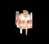
Ya know those variable capacitors that are tuned with a screwdriver, like in the picture? Has anyone ever been able to put a knob over one somehow? I guess I could use some superglue or something. any ideas?
I've had superglue eat through plastic before, so if its a plastic knob, I'd not do that. Perhaps you could use some standard good ol' Elmer's, let it sit for an hour and hope it sticks? If that top is metal, perhaps you could solder some kind of metal knob to it?
Epoxy would be the best bet, if you want to try
that method.
I would suggest: get a proper tuning tool, find
a sleeve that fits snugly around the shaft AND
the rotor tip (possibly heat-shrink tubing), then
find another sleeve that fits around the base of
the whole cap, and something to fill the space
between the two, full but not tight.
These are relatively fragile, and will not take
much abuse. Attempts to solder to the post,
while easily done, will undoubtedly ruin the
cap. Plus, the caps are not designed to be
often used - the construction is simple and cheap.
If you can find its ceramic cousin, the whole
top cover rotates, and it is possible to use
it as a grip, although tuning is difficult since
the fingers affect the circuit tuning.
Can you not find a suitable value with the
knob inherent? Small transistor radios might
yield up a usable substitute.
No, to many other metals as well - and that's just 'normal' solder, special solders are available that handle stainless steel and aluminium.
But 'normal' solder easily works on gold and silver (commonly used as plating on component leads and pins), and also to lead, plus various other metals.
The screw on a trimmer would probably solder VERY easily, the only problem is the heat melting the body.
How about just using a variable capacitor?, instead of a preset one?.
Everything on that cap other than the plates and the screwdriver adjustment is made of metal, so soldering will be a delicate operation or everything will turn into a plastic blob. The adjustment shaft is most likely brass and easily solderable. To solder, use another brass rod of the same diameter and cut a short screwdriver protrusion into it with a small file to engage the slot on the cap. Grab the base of the caps shaft with needlenose pliers to act as a heat sink. Carefully use a file or emery cloth to brighten up the face of the cap shaft and quickly tin the face with solder. Tin the face of the extension shaft, bring it up to temperature and engage the two parts in good mechanical alignment. It wouldn't hurt to have a damp sponge handy for quickly cooling the joint.
However, using a brass extension on a trimmer may induce a new problem. Depending upon the circuit and how the cap is installed on the PCB, the action of adding the shaft, adding a knob or bringing your fingers around the knob may shift the capacitance value. To fix this, you'd better use the plastic-shaft-installed-using-epoxy route. Cut that same short screwdriver blade in the extension shaft as well.
Cutting the screwdriver blade into any extension shaft will be like using a finger joint for wood gluing -- you add more surface area to the joint to make it stronger. A straight butt joint will be very weak. I know ... for a lot of you guys, there's no difference between a butt and a joint. Think "woodworking" here, not recreational inhaling.
Oh yeah!! How could I be so stupid!?! I have a broken pocket radio with the perfect capacitor and knob.
And it's MEANT to be adjusted all the time, unlike the capacitor i'm tlaking about. I've had one of those break on me one time because of excessive use.
The shaft of the capacitor appears to have a groove around it.
If you obgtain a length of brass tubing with an internal diameter which just slips onto the shaft you could make an extension from it.
Cut slots in one end so that it has four "fingers" which can me bent in slightly to grasp the groove in the shaft. Apply a little super-glue in gel form prior to asembly.
You should also put a solid slug of whatever you can find to fit in the tube at the other end where the knob sits to prevent the tube collapsing under pressure from the grub-screw.
Zach, the cap from the transistor radio that you're pursuing will have anywhere from 10 to 100 times the maximum capacitance of the trimmer that you illustrated. That can make it very difficult to adjust if a portion of its range happens to cover what you need. In addition, its minimum cap value may actually be MORE than the maximum cap value of the trimmer, making it difficult to use in your original circuit unless you slide another cap in series with it.
Zach, the cap from the transistor radio that you're pursuing will have anywhere from 10 to 100 times the maximum capacitance of the trimmer that you illustrated. That can make it very difficult to adjust if a portion of its range happens to cover what you need. In addition, its minimum cap value may actually be MORE than the maximum cap value of the trimmer, making it difficult to use in your original circuit unless you slide another cap in series with it.
Assuming it's an AM/FM radio, you use the FM (VHF) side, which will give the perfect value and range for the FM transmitter. There should be four variable capacitors in the tuning capacitor, two high capacitance for AM, and two low capacitance for FM.
If it's an AM only radio, as Dean says, it will be far too high a value.
This site uses cookies to help personalise content, tailor your experience and to keep you logged in if you register.
By continuing to use this site, you are consenting to our use of cookies.