Continue to Site

Welcome to our site!

Electro Tech is an online community (with over 170,000 members) who enjoy talking about and building electronic circuits, projects and gadgets. To participate you need to register. Registration is free. Click here to register now.

  • Welcome to our site! Electro Tech is an online community (with over 170,000 members) who enjoy talking about and building electronic circuits, projects and gadgets. To participate you need to register. Registration is free. Click here to register now.

Vanity light electrical wiring.

Status
Not open for further replies.

Chrissy Chac

New Member
Hi!! I am a newby here with my first thread and I am hoping that one of you can help me. I was trying to switch my bathroom light fixture to a new one. I am not very electrical savvy so I watched many YouTube videos on how to do this lol. It looked simple enough-remove the existing light fixture and add attach the ground wire to the green screw then attach the white wires together as well as the black ones.
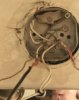
When I began to remove the existing fixture I noticed that not only do I not have any black wires, but I have many white ones and one red.
Do I just attach the black wire to the red one?
 

Attachments

  • 2845F40E-2AEB-49AB-B772-4AFB987C1A53.jpeg
    2845F40E-2AEB-49AB-B772-4AFB987C1A53.jpeg
    694 KB · Views: 169
Yes. White should indicate neutral. Black usually indicates the load side. Other, non-white, colors usually indicate a switched load side connection.

In the future, when replacing fixtures, take note of how the current one is connected and re-connect the new one in the same way.
 
Yes. White should indicate neutral. Black usually indicates the load side. Other, non-white, colors usually indicate a switched load side connection.

In the future, when replacing fixtures, take note of how the current one is connected and re-connect the new one in the same way.
Thank you !! I realized that I should’ve taken a picture of the original wires after I removed the second screwy thing. I will definitely take your advice and remember that for future use.
Do you know what I do with the wire that looks like a ground wire that is inside the box also.?
 
Thank you for replying. No, it is a bathroom vanity light fixture that only has one switch but the switch for the exhaust fan is next to it.
 
Yes. White should indicate neutral. Black usually indicates the load side. Other, non-white, colors usually indicate a switched load side connection.

In the future, when replacing fixtures, take note of how the current one is connected and re-connect the new one in the same way.
I believe that is what you have. The whites are neutral, when ground exist it is normally green, green yellow striped or bare copper and the red wire should be the switched power. The black wire on the fixture would be tied to the red wire in the box.

Commonly called the "hot" it may be a switched black or sometimes they run black to the switch and red from switch to fixture.

Ron

Ron
 
Thank you !! I realized that I should’ve taken a picture of the original wires after I removed the second screwy thing. I will definitely take your advice and remember that for future use.
Do you know what I do with the wire that looks like a ground wire that is inside the box also.?

If you are talking about the third wire (the one that is NOT black or white) on your new fixture, that should be a ground as you thought. Loosen the screw in the junction box that has the other wire looped under it (at about the 2:00 position), wrap the fixture wire around the screw CLOCK-WISE, and tighten.

The reason you wrap it clock-wise is so, when you tighten the screw (turning it clock-wise), the wire gets drawn into the screw.
 
Thank you Spudboy for your reply. Here is a picture of what is with the new fixture. So, white with white, black with red and the ground on the green screw or the ground at 2:00 like you suggest?
 

Attachments

  • 2092BDE2-60E9-4BFD-8A0C-2EC8FEA1C8EA.jpeg
    2092BDE2-60E9-4BFD-8A0C-2EC8FEA1C8EA.jpeg
    488.7 KB · Views: 117
Not sure if anyone mentioned but be careful, the red circle is of your black (hot wire) where its been painted white.
hothothot.jpg


Is this on a 3 way light switch? there are a lot of different ways to hook up but this is a common one,
how-to-wire-3-way-switch-2.jpg
 
Last edited:
Thank you Spudboy for your reply. Here is a picture of what is with the new fixture. So, white with white, black with red and the ground on the green screw or the ground at 2:00 like you suggest?

You can tie the ground wire to the green screw on your bracket as long as the bracket gets screwed into the junction box with metal screws. If in doubt and probably preferred, loop it around the screw as I mentioned.

(To answer narkeleptk's concern) When you took the old fixture out, did you pull the white wire from the bundle (inside the screwy thing) in the red circle in their picture? Did it, by chance, have black tape on it as well?

(To answer my question possibly related to narkeleptk's) At the bottom of your first picture, there are 3 wires in a wire nut (screwy thing). Where does the wire leading out of frame head off to?
 
Last edited:
The white wire leading out of the frame that is still in the screwy thing is still attached to the old fixture as this is when I realized I had an abundance of white wires. So I did not pull the white wire out of the bundle. That bundle just has the screwy thing removed.
Thank you again !!
 
This seems wrong on so may accounts. For one the wires should enter as cables and strapped in via the two clips on the top and bottom of the picture. The other way is through the knockouts. You can use the center knockout and there is a dual romex . US anyway, there are dual NB-B clamps (https://www.ecmweb.com/qampa/stumped-code-2)

I will assume that US and Canada are similar.

it may not be wired with NM-b. Wires just poked through holes doesn';t make any sense.

The ground screw (The widest head) isn't green, but it's there. Ideally, the grounds should be tied together and wirenutted and tied to the box and fixture. I've had a ground loose it;s connection when connections are made that way. The looped-through grounds are the ones that need a wirenut. That bundle can be tied to the box and/or the fixture tied to the box usually with a fork ground pigtail.

Who knows if it's wired with NM-b (Romex -brand).

Usually you would expect two cables (white, black and a solid ground). You either feed from the switch or feed from the light.

When coming from the switch, you would tape the white wire black (change it's color).

I'm also wondering if this is a "shared neutral" situation. GFCI breakers won;t work with a shared neutral.

Wires poking through a single hole unprotected by an outer jacket is asking for trouble.
 
Thank you for everyone’s replies !! I’m just going to hire an electrician for this. I appreciate everyone taking the time to help me with this.
 
Looks pretty basic to me in the US. The only problem is the white over-spray because someone did not tape it off when painting.
Two Hots twisted together (black with the white paint covering it) Top of picture.
Two neutral twisted together (actual white casing) bottom center of picture,
bare ground screwed in to housing
and the red traveler wire for a 3 way switch(with some over-spray paint to) .
Also, The black and white leads coming from fixture in the very bottom of picture with neutral still twisted together..

Our grounds are usually bare in the walls and green casings on fixtures in my experience.
 
Last edited:
Don't Canada and USA use green (or green/yellow) PVC sleeving over bare earth (ground) wires. To me, in the UK, this wiring looks very scary!


It looks scary to me (in the US) because of the wires poking through the small holes.

My father (actually trained as an electrician) did some wiring at home that eventually haunted me. An outlet lost a ground all because the grounds were twisted but not wire-nutted. Eventually an oxide formed and no ground for down stream outlets.

In the 1960's house, the 120V outlets were two prong polarized. A ground was run to the outlet and the outlets had metal plates, Upgrading was a little bit of a pain because no ground screws existed in the 1960's and the box and outlet have to be grounded separately.
There is a ground clip available that will mechanically attach a solid wire to the edge of the box. There are ground pigtails.

there are these
119499


things.

and these

119500


This would be used to attach to the ground lug of the outlet itself.

These

119501


are not made anymore. They came in white, black and green with or without the fork terminal. I really liked them.
You could do the black/white daisy chain and the ground connection and connect to the outlet really easy with the fork terminal.
The other end is a wirenut.

This **broken link removed** link shows the powertails which could be a decent substitute for termanuts. Then there is the ground clip and the various ground wire pigtails.

New work in a modern box with a tapped ground hole, it all 1563569959381.png1563570027217.png1563570279125.pngworks out.
1563569959381.png1563570027217.png1563570279125.png
 
Status
Not open for further replies.

Latest threads

New Articles From Microcontroller Tips

Back
Top