Continue to Site

Welcome to our site!

Electro Tech is an online community (with over 170,000 members) who enjoy talking about and building electronic circuits, projects and gadgets. To participate you need to register. Registration is free. Click here to register now.

  • Welcome to our site! Electro Tech is an online community (with over 170,000 members) who enjoy talking about and building electronic circuits, projects and gadgets. To participate you need to register. Registration is free. Click here to register now.

Vacuum tube oscilloscope sweep generator

Status
Not open for further replies.

SGiard

Member
Hi, can anybody help me figure out the process by which the sweep cap (which is connected between the cathode of v6-a and ground, IF I understand correctly) gets discharged in that schematic? I don't know tubes much but I think I understand why it charges (there is current flow between plate and cathode of v6-a). But even if you stop current flow by turning the grid negative, the way I understand it, it will stop the cap charging but not discharge it. I just don't see the discharge path. Help!!!
 

Attachments

  • hickock-schematic.jpg
    hickock-schematic.jpg
    125.9 KB · Views: 657
Hi SG,

Boy that circuit diagram brings back memories of some scopes I had in the 1960s.

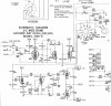
You don not include the time-base capacitors in the schematic, but all scope ramp generators rely on charging/discharging a capacitor with a constant current to generate a linear voltage ramp

From what I can tell V6a acts like a switch which is activated by a trigger input.

When V6a cathode is positive that holds the timing capacitor at a fixed voltage, which would correspond to the dot on the scope CRT screen being at the left.

When the cathode of V6a goes negative, V6b no longer conducts, so no current flows into the timing capacitor from V6b.

But there will be a constant current generator that will remove current from the timing capacitor. If you remove a constant current from a capacitor, you generate a negative going linear ramp voltage across the capacitor.

Just in case you want to know, the rate of change is given by the formula, dV = C/I, where dV is the rate of change of voltage across the capacitor in Volts, C is the capacitance in Farads, and I is the current in amps.

So take a practical example:

You want the trace to move horizontally at one division per second on the CRT display and each division equates to 1V at the time base generator when you take into account the horizontal amplifier gain (V7 and V8 on your scope).

The minimum constant current your circuit will generate is 100uA say, so the value of timing capacitor would be calculated from C = (I * T)/V = (100uA * 1s)/1V = 100uF.

To change the time-base rate on a scope you just juggle the timing capacitors and the constant current. Typical constant currents would be, 100uA, 200uA, and 500uA.
and these are switched in by the time-base rate selector switch along with the appropriate timing capacitor. These three constants currents would give the often-used 1...2...5 time-base ratios.

When the negative going saw tooth voltage across the timing capacitor reaches a low enough voltage to turn V6a on via its cathode (this corresponds to the dot on the CRT screen being at the right (correction 2016_12_01) of the screen), V6a will snap on again and restore the dot to the left of the screen awaiting for the next trigger (I think that V5 and V6a are a Schmitt trigger).

It is as simple as that.:)

2016_11_23_Iss1_ETO_SCOPE_TIME-BASE_VER1.jpg

spec
 
Last edited:
I think the discharge path for the sweep timing capacitor is to ground via R56 and potentiometer R59 . I think R56 will be connected to the selected timing capacitor via the right hand part of the range selector switch when the left hand part is in one of the positions selecting one of the range capacitors. I think when R59 is in its zero resistance position this will be the "calibrated " position and moving R59 away from its zero resistance position will slow the sweep down.

Les.
Yes, it does look that way, but that would not give a linear sweep?
I was imagining that the timing capacitors and constant generator were on another part of the circuit and that V6b is the timing gate (switch).

spec
 
hi,
V5 and V6a form a cross coupled CC gen, without sync the CRT beam trace will not run

E
 

Attachments

  • hickock-schematic.jpg
    hickock-schematic.jpg
    126.6 KB · Views: 340
I think V5 and V6A form a multivibrator. This is how I think it works. We will start with V6A conducting. V5 will not be conducting at this point. (This half cycle is the flyback.) When the capacitor (Selected by the range switch) is charged there will be no cathode current in V6A so the anode current will drop and hence the anode voltage will rise. This will be passed via C14 to produce a positive voltage on the control grid making V5 conduct whic will cause the voltage on the control grid of V6A to drop. The capacitor selected by the range switch will then start to discharge via R56 and R59. This is the scan part of the cycle. I think they must just use part of the exponential discharge to approximate a straight line. There does not seem to be any attempt to provide a constant discharge current. When I first saw the circuit I thought it was going to be a miller intergrator. I remembered from over 50 years ago which was when I last built a valve scope that this was what was normaly used in timebases. I could not remember the circuit so I Googled "Miller integrater valve" The circuit in this scope did not seem to match any of the examples. (Most of which were transistor circuits even though I included the word valve in the search.

Les.
 
Last edited:
I think V5 and V6A form a multivibrator. This is how I think it works. We will start with V6A conducting. V5 will not be conducting at this point. (This half cycle is the flyback.) When the capacitor (Selected by the range switch) is charged there will be no cathode current in V6A so the anode current will drop and hence the anode voltage will rise. This will be passed via C14 to produce a positive voltage on the control grid making V5 conduct whic will cause the voltage on the control grid of V8A to drop. The capacitor selected by the range switch will then start to discharge via R56 and R59. This is the scan part of the cycle. I think they must just use part of the exponential discharge to approximate a straight line. There does not seem to be any attempt to provide a constant discharge current. When I first saw the circuit I thought it was going to be a miller intergrator. I remembered from over 50 years ago which was when I last built a valve scope that this was what was normaly used in timebases. I could not remember the circuit so I Googled "Miller integrater valve" The circuit in this scope did not seem to match any of the examples. (Most of which were transistor circuits even though I included the word valve in the search.

Les.

Hi Les and Eric,

Maybe the circuit just uses a fairly linear part of a CR exponential wave form, but that would be strange.

By the way, a simple miller integrator comprises a valve (tube) with a capacitor connected between the anode and control grid. Then you put a resistor between the control grid and the input to the Miller integrator. The capacitor then gets a constant constant current charge/discharge if you feed the circuit with a square wave.

spec
 
Thanks a lot for the replies. I'm going to have to study all of that for a while. I'm posting the whole schematic in case any of you are curious.
 

Attachments

  • hickock-schematic.jpg
    hickock-schematic.jpg
    298.6 KB · Views: 313
Thanks a lot for the replies. I'm going to have to study all of that for a while. I'm posting the whole schematic in case any of you are curious.
Thanks- the scope is a lot simpler than I thought. I forgot to ask; is this just out of interest or are you trying to fix a fault on the scope?

spec
 
I'm actually rebuilding it. I love old vacuum tube scopes. I'm just in awe of them. I had bought that scope at a flea market 4 years ago. They are kind of rare around here. It worked for a while then the transformer caught fire. Since I did not have a replacement, I built a new power supply based on a 800V transformer and a voltage doubler. That worked for a while until one of the caps in the doubler sparked big time and blew the heater of the CRT. At that point I scrapped it for the parts and forgot about it.

I recently found an old Heathkit ignition analyzer at another flea market. The thing did not work but there was a green dot sitting there in the middle of the screen once I replaced the fuse. It actually has the same CRT and a working power supply so I got the idea of recreating the Hickok with the original parts but to build each section on a separate PCB and hook them together. The sweep is the last section but I'm having a lot of trouble with it so I thought maybe there was a mistake in the schematic. It is also the section that is most complex for me so I wanted to understand it more. I uploaded a picture of what it looks like so far.

I really appreciate the very detailed answer and I'm still trying to wrap my head around it. I would have never guessed that it was a descending voltage ramp.
 

Attachments

  • IMG_5482.JPG
    IMG_5482.JPG
    251.5 KB · Views: 313
I'm actually rebuilding it. I love old vacuum tube scopes. I'm just in awe of them. I had bought that scope at a flea market 4 years ago. They are kind of rare around here. It worked for a while then the transformer caught fire. Since I did not have a replacement, I built a new power supply based on a 800V transformer and a voltage doubler. That worked for a while until one of the caps in the doubler sparked big time and blew the heater of the CRT. At that point I scrapped it for the parts and forgot about it.

I recently found an old Heathkit ignition analyzer at another flea market. The thing did not work but there was a green dot sitting there in the middle of the screen once I replaced the fuse. It actually has the same CRT and a working power supply so I got the idea of recreating the Hickok with the original parts but to build each section on a separate PCB and hook them together. The sweep is the last section but I'm having a lot of trouble with it so I thought maybe there was a mistake in the schematic. It is also the section that is most complex for me so I wanted to understand it more. I uploaded a picture of what it looks like so far.

I really appreciate the very detailed answer and I'm still trying to wrap my head around it. I would have never guessed that it was a descending voltage ramp.

I love scopes too, and always wanted two things, even as a nipper: scope and a lathe. Both were way beyond my comprehension and price range.

But from 1967, I spent about 25 years designing/building/refurbishing scopes, firstly valve (tube) and then transistor. One of the most impressive scopes I had was an EMI WM26, complete with trolley. It was around 18" by 18" by 24" and consumed about 600 Watts, if I remember correctly.

In the end I bought a faulty Gould OS1000A scope (like pic below} for £5UK and, once the EHT was fixed, that was my scope for years untill it got crushed in an accident. Now I have a 1990 Tektronix 2235A, bought from ebay USA.

Your scope is very simple, as scopes go, so it should be possible to get it running. By the way, what is the model number. Do you have a picture of the front showing the controls?

spec

general_purpose_oscilloscope_514750.jpg
 
Last edited:
Yeah lathes are fun too!

It's a Hickok OSK-4. I posted a picture of it. I wish mine was in such good shape, though. It is a simple scope, that's why I thought I could manage rebuilding it. Once I am done with recreating the original, I'll make it so I can switch out the sweep and replace it with a design I have in mind that would make the scope dual trace. Just for fun.
 

Attachments

  • hickok-osk-4-s-40-1437_orig.jpg
    hickok-osk-4-s-40-1437_orig.jpg
    56.1 KB · Views: 311
hi SG,
This is a rough LTSpice sim of the Ramp gen circuit, I had to use a Triode in place of the Pentode. [ my Pentode model has a problem!]

E
 

Attachments

  • A01.gif
    A01.gif
    34.5 KB · Views: 314
Thanks E. Wow, this is fascinating!

I'm still not 100% clear why that circuit behaves the way it does. Let's refer to your circuit. Please tell me if i got that correctly:

The first two steps are based on spec's explanation,

With U1 off (not conducting) C4 discharges thru R8
When voltage is low enough, U1 turns on

... then ... (my understanding)

That pulls up the voltage at the top of R6
That turns U2 on
That lowers the voltage at the bottom of R3
That makes the grid of U1 negative, which turns U1 back off
That lets C4 discharge thru R8 again and the cycle repeats

Did I get that correctly?
 
Last edited:
hi,
You can see from A03.gif plots that the two valves/tubes act as a Astable switch, when U1 is On, U2 is Off and vice versa.
When U1 is On the Cathode current charges up C4, when U1 is Off the cap discharges via R8.

I have chosen C4 and R4 to suit the simulation and shown the full range of the C4 voltage, this shows an overall non linear discharge versus time.

In the actual Scope only the first section of the C4 discharge voltage is used to drive the Scope Y plate deflection as the 'linearity' is considered acceptable over this limited range.

For info only the A02.gif plots show the effect of applying an external Sync pulse to U2 Grid.

E

EDIT:

A02.gif I have added a Black line on a Synced and Non Synced discharge path to emphasis the linearity difference.
 

Attachments

  • A03.gif
    A03.gif
    42.3 KB · Views: 289
  • A02.gif
    A02.gif
    39.6 KB · Views: 298
Last edited:
I intended to keep the originals as a first step (see picture). Any recommendations on what I should use if I ever change them?
 

Attachments

  • Caps.JPG
    Caps.JPG
    734.1 KB · Views: 304
I intended to keep the originals as a first step (see picture). Any recommendations on what I should use if I ever change them?
Polypropylene are the Rolls Royce capacitors.:cool:

spec
 
To complement what spec mentions, if you do use ceramic caps, employ exclusively class-I ceramics (NPO, COG).
Stay away :eek: from class-II ceramics. (X7R, Y5V)
 
Status
Not open for further replies.

Latest threads

New Articles From Microcontroller Tips

Back
Top