Yes it is possible for damage to occur as the tube type radio's used a step down audio transformer. With out a reasonable load the secondary, where the normal speaker connnected the reflected impedance in the primary was very high.
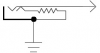
A normal solution is to use a 1/4 jack that has a switch contact built in to the jack. The contacts are normally closed with out a plug in the jack, thus putting a load on the secondary. When a plug is inserted into the jack the contacts open disconnecting the load, and the load on the plug now becomes the load on the secondary.
See the attached figure.
Attached Thumbnails
__________________
The great thing about electronics is unlimited ways to do the job. The only limit is one\'s imagination. I generally think my way is best.
Show me a different way. I have an open mind.