Continue to Site

Welcome to our site!

Electro Tech is an online community (with over 170,000 members) who enjoy talking about and building electronic circuits, projects and gadgets. To participate you need to register. Registration is free. Click here to register now.

  • Welcome to our site! Electro Tech is an online community (with over 170,000 members) who enjoy talking about and building electronic circuits, projects and gadgets. To participate you need to register. Registration is free. Click here to register now.

UV Exposure Box

Status
Not open for further replies.

Magen

New Member
Hello everybody,
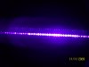
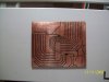
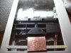
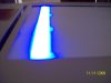
I am building the above from an old discarded flatbed scanner and have most of it working. It comprises about 36 leds in a row which replaces the flourescent that was in the scanner. The motor is now driven by a 16F628 pic. All works well but I would like to know what I could use for shielding as, when the leds are on, I am unable to stand near the scanner without becoming nauseus. I think it's from the uv radiation being produced and would like to make the box safer.
Any suggestions welcome.
 
UV radiation, didnt know there was such a thing, uv can only travel a certain distance before it becomes ineffective and as far as i am aware, UV cannot travel through glass.

can you actally see the UV light from the leds??
 
Hi cobra1,
Yes, see attached pics. UV works through glass.
 

Attachments

  • Picture7 041.jpg
    Picture7 041.jpg
    1 MB · Views: 403
  • Picture7 044.jpg
    Picture7 044.jpg
    1.1 MB · Views: 316
  • Picture7 045.jpg
    Picture7 045.jpg
    1.1 MB · Views: 303
You might want to put some kind of diffuser on it to avoid bright/dim spots, the brightness loss isn't too much of an issue as you can just let it stay under it longer. We can't see the UV but we can see the portion of it that extends into the upper Violet range, the primary frequency it puts out is invisible to the human eye. If you put a UV light next to something that fluoresces under UV light you'll notice how much brighter it is than the apparent UV source, and that's a secondary reaction.

Cobra, I'm not sure why you think UV is so limited, it's nothing more than a colour of light that's just outside our visual range, birds have been shown to be sensitive to UV light, and can see interference patterns in the day sky cause by UV light diffraction patterns as part of their geolocation systems. That's UVA though, you may be thinking UVB or farther up the UV spectrum, down actually as it goes clear on down to 10nm's. UVA is only 400-320nm
 
Last edited:
Hi Magen,

I wonder where you left the original lid of the scanner. Exposing PCB material the lid should be used to avoid UV-light causing (most probably severe) eye damage. Put some extra weight on the lid to have it press the film and the PCB well on the glass.

If you want to learn more about the abilities of UV-light contact the sales manager of Seoul semiconductors. He lost vision of one eye completely looking at an UV-LED radiating at 340nm (UV-A) and a forward current of 100mA.

Boncuk
 
One of the reasons I suggested a diffuser. Something as simple as a thin sheet of tissue paper will diffuse the light very well. Again power isn't the issue, the frequency of the light is what's supposed to do the work.
 
Last edited:
Hi Guys,
I do have the cover for the scanner and use it whenever I use the scanner.You cannot see anything when the lid is closed. What bothers me is what UV I cannot see. There isn't really a problem with diffusion. I think the pic I took is misleading.See attached. I placed the led's as far down as I could so the coverage ended up pretty good. I still busy with the circuit so I think I'll add a beeper and led to indicate when the led's are on and keep away from them.
 

Attachments

  • Picture7 047.jpg
    Picture7 047.jpg
    810.3 KB · Views: 366
what is the purpose of the UV scanner? i'm not sure i understand what you're attempting to achieve? pardon my ignorance.
 
Hi Sirmikey,
I use it to manufacture pcbs at home. Using the scanner like I am saves me buying more leds to cover the larger area, plus I'm learning to use microcontrollers so it's a nice 'beginners project' for me.:)
 
what is the purpose of the UV scanner? i'm not sure i understand what you're attempting to achieve? pardon my ignorance.

The OP also posted a headline "UV exposure box".

You can't beat the quality of an UV-exposed PCB compared with toner transfer.

It is next to a Gerber photoplot.

If you want top quality for a "film" use positive UV sensitive film and make a contact copy of the original laser print from the transparency of a PCB layout. The positive film fills all "blind" spots being produced by the laser printer.

I used that method using negative sensitive film for double sided PCBs with plated throughholes and differential etching.

Boncuk
 
You might want to put some kind of diffuser on it to avoid bright/dim spots, the brightness loss isn't too much of an issue as you can just let it stay under it longer. We can't see the UV but we can see the portion of it that extends into the upper Violet range, the primary frequency it puts out is invisible to the human eye. If you put a UV light next to something that fluoresces under UV light you'll notice how much brighter it is than the apparent UV source, and that's a secondary reaction.

Cobra, I'm not sure why you think UV is so limited, it's nothing more than a colour of light that's just outside our visual range, birds have been shown to be sensitive to UV light, and can see interference patterns in the day sky cause by UV light diffraction patterns as part of their geolocation systems. That's UVA though, you may be thinking UVB or farther up the UV spectrum, down actually as it goes clear on down to 10nm's. UVA is only 400-320nm

hi sorry, i didnt word it properly. it was UVB i was thinking of.
i keep reptiles so have had to use UVB tubes at times. this is what i was thinking of in this situation.

are those leds your using the equivalent of "black Light" they look pretty cool actually
 
Txs Cobra1, I think they are the equivalent of a pure UV Tube, so they are dangerous. The black light as I understand it gives off the uv colour we see but is not as dangerous. Blacklights have the black coating whilst the pure uv tube is clear.
 
cobra1, I had no idea reptiles benefited from UVB lights, interesting. UV LED's while a little less common should cost the same as a typical bright white LED as generically they're the same thing white ones just have phosphor on them that converts the UV to the different colours of lights.
 
@ Boncuk,
Do you produce through hole plated boards at home?

Hi Magen,

I did back in Germany. The machine was designed by Isel automation and required close watch of each step, mainly the plating process. Vias and troughholes had excessive cupper build up at the hole entries and exits quite often (looking like craters). Interrupting the process for a while lead to sufficient results, still not knowing the final copper weight.

The copper clads had a layer of 5µm to add another 30µm on traces and in holes. Plating by timing was just a rough guess.

Bungard offers a better machine indicating the growth of copper digitally. It also uses reverse pulsing during plating to avoid excessive copper buildup at holes. I still have to save some money to buy it.

Boncuk
 
Regardless of the methods used vias and plating depositing in electrolytic operations is always a pain. It's just the way it works. Most people would be surprised how uneven typical plating actually is.
 
I worked at a college (in the workshop) a long while back and remember what their through hole plating line looked like. Several 'baths' with a lot to be monitored and the very strong smell of amonia (for the developing). The plating ended up pretty good but I was told if the line isn't kept running, it becomes a head ache to maintain.
 
Yeah, typically plating baths like to be used, intermittent use lends itself to a lot of headaches.
 
Status
Not open for further replies.

Latest threads

New Articles From Microcontroller Tips

Back
Top