TheEquineFencer
New Member
ericgibbs said:hi Floyd,
Looking thru your drawing, one or two queries.
What current are you expecting thru opto TX diode when LED11 is lit?.
What current are you expecting thru the opto RX transistor when LED11 is lit?
Check the opto current transfer function.
You do realise that the TIP/Solenoid will be OFF when only LED11 [last LED] is lit.
If you plan to switch 8 solenoids, ie about 10Amp, have you checked that the two switches in series
with solenoids can handle 10Amps?. [ 'full-opon' and 'on-rise' contacts]
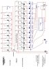
I believe that pin #3 of the LM3914 is going to the wrong end of R1 [10K] ,also whats the purpose of R1?
The LED current sinks of the LM3914 are constant current, fixed by R2 [680R]
Where is the 0V/Gnd connection for pin #8/#2 of the LM3914?
Who drew the circuit?
Eric
EDITED: viewed the pcb layout you posted on another thread, from which I was able to clear some of the questions in my post.
re-font as italic
I]What current are you expecting thru opto TX diode when LED11 is lit?.
Ans.1
Question #1 On the drawing it says LED#11, it's really #10, I have not a clue as far as Tx, not even what you mean, I'm really new at this and just picked an OPTO I thought would work. The only load going through the LED side is 10-20ma to turn the LEDs on as far as I know.
What current are you expecting thru the opto RX transistor when LED11 is lit?
Ans.2
Same as #1
Check the opto current transfer function
Ans.3
I have not a clue what you mean by that
You do realise that the TIP/Solenoid will be OFF when only LED11 [last LED] is lit.
Ans.#4
Yes, that is my purpose. I plan to have an OPTO attached to EACH LED and then have a dip switch so I can select which level of O2 I want to start cutting the solenoids off at.
If you plan to switch 8 solenoids, ie about 10Amp, have you checked that the two switches in series
with solenoids can handle 10Amps?. [ 'full-opon' and 'on-rise' contacts]
Ans#5
Now that you mention it, I really did not even think of the load on the supply going to the injector circuit through the two NO contacts on the limit switch and the pressure switch, thanks, I'll use a relay for that load.
I]Where is the 0V/Gnd connection for pin #8/#2 of the LM3914? [/I
Ans#6
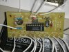
I'm not really sure, the directions I was given for this ciruit had me make the connections as shown, I might have misplaced something on the drawing when I tried to look at the actual board and put it into the drawing, but the board does work as designed. O2 level goes up/down, the LEDs follow.
Who drew the circuit?
Ans #7
The drawing on the post I tried my best to do with a program disk I was given for a class they do at school. The actual circuit is from a
O2 Monitor/Voltage monitor design that can be purchased on the Internet.
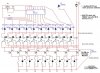
Now I have another question, in the drawing you posted, what is the purpose of the 10000uF,16V Zener and the 10K R connected on the +12V/0V Grd side?
When I run the S1 with the Dc blocking/clamping diode Will I need to do the same to each of the njectors I plan to run off each FDS4935As. I'll go back and reread your post again, I was up at 3am EST to go on a fishing trip and just got home. I now have to replace the turbocharger on my GF's truck to top it all off, the impeller is coming apart.
 hm: resistor not 10K.