Electro Tech is an online community (with over 170,000 members) who enjoy talking about and building electronic circuits, projects and gadgets. To participate you need to register. Registration is free. Click here to register now.
Welcome to our site! Electro Tech is an online community (with over 170,000 members) who enjoy talking about and building electronic circuits, projects and gadgets. To participate you need to register. Registration is free. Click here to register now.
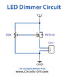
ran across this schematic and thinking of incorporating into my next sign PCB.
QUESTION maybe a 1K resistor before the gate to protect the gate?
Planning on using a smd pot
ran across this schematic and thinking of incorporating into my next sign PCB.
QUESTION maybe a 1K resistor before the gate to protect the gate?
Planning on using a smd pot
after some research, the most the mosfet will have to handle is approx 5 watts.
The pot will be hard wired to the PCB. The company selling the LED/neon rope lights has a dimmer that can be used. Will consider
after some research, the most the mosfet will have to handle is approx 5 watts.
The pot will be hard wired to the PCB. The company selling the LED/neon rope lights has a dimmer that can be used. Will consider
You can use a PWM circuit to drive a power FET high (P)ch) or low side (Nch) such as a LM555 PWM with a pot. Then it will be efficient. Choose f = 1k to 5 kHz or buy a proper remote control controller with LEDs is best.
FWIW, the 28-pin 18F2221 has two CCP/PWM peripherals... CCP1 and CCP2.
CCP1 output is on pin RC2, and CCP2 output can be either RC1 or RB3 depending on the CONFIG CCP2MX setting.
This site uses cookies to help personalise content, tailor your experience and to keep you logged in if you register.
By continuing to use this site, you are consenting to our use of cookies.