strokedmaro
New Member
Hello...Im pretty new here and have gotten a lot of help from some of you already which I really appreciate. Ive got a pretty basic background in electronics but am able to read a mean schematic and pick up really quick on things I'm interested in.
I recently undertook a fairly simple project and with a little research and reading have figured out how to make it work with transistors and gates. The problem is it requires so many components to work. I was told that not only would a PIC be cheaper but it would require far less components to operate.
Ive tried to figure this out on my own but the information I've found is primarily for someone who has a clue to begin with. Please let me know what I should buy to get started. Keep in mind I know absolutely nothing about the process but this is what I hope to be able to achieve:
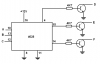
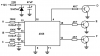
I need a way to take 3 separate input voltages of 12vdc in 3 combinations and either have 1 ground (preferred if possible) or 1 voltage output on 3 different pins. Here is my table:
INPUTS_________OUTPUTS
A: 12vdc_______D: ground (or voltage)
B: 12vdc_______E:
C: 12vdc_______F:
INPUTS_________OUTPUTS
A: 12vdc_______D:
B: 12vdc_______E: ground (or voltage)
C: 0vdc________F:
INPUTS_________OUTPUTS
A: 12vdc_______D:
B: 0vdc________E:
C: 0vdc________F:ground (or voltage)
Please let me know if this is even possible, what equipment and PIC you would recommend that would work with this application. Also, any links to any information that will help the newest of the new guys understand. (I was directed to a sticky somewhere on this forum but again, most info was for more advanced people)
I really want to figure it out on my own and if I have the equipment, PIC and a little knowledge provided from some more experienced people I know I can make it work eventually. THANKS IN ADVANCE FOR ANY INFO YOU PROVIDE!!!
I recently undertook a fairly simple project and with a little research and reading have figured out how to make it work with transistors and gates. The problem is it requires so many components to work. I was told that not only would a PIC be cheaper but it would require far less components to operate.
Ive tried to figure this out on my own but the information I've found is primarily for someone who has a clue to begin with. Please let me know what I should buy to get started. Keep in mind I know absolutely nothing about the process but this is what I hope to be able to achieve:
I need a way to take 3 separate input voltages of 12vdc in 3 combinations and either have 1 ground (preferred if possible) or 1 voltage output on 3 different pins. Here is my table:
INPUTS_________OUTPUTS
A: 12vdc_______D: ground (or voltage)
B: 12vdc_______E:
C: 12vdc_______F:
INPUTS_________OUTPUTS
A: 12vdc_______D:
B: 12vdc_______E: ground (or voltage)
C: 0vdc________F:
INPUTS_________OUTPUTS
A: 12vdc_______D:
B: 0vdc________E:
C: 0vdc________F:ground (or voltage)
Please let me know if this is even possible, what equipment and PIC you would recommend that would work with this application. Also, any links to any information that will help the newest of the new guys understand. (I was directed to a sticky somewhere on this forum but again, most info was for more advanced people)
I really want to figure it out on my own and if I have the equipment, PIC and a little knowledge provided from some more experienced people I know I can make it work eventually. THANKS IN ADVANCE FOR ANY INFO YOU PROVIDE!!!
Last edited: