Continue to Site

Welcome to our site!

Electro Tech is an online community (with over 170,000 members) who enjoy talking about and building electronic circuits, projects and gadgets. To participate you need to register. Registration is free. Click here to register now.

  • Welcome to our site! Electro Tech is an online community (with over 170,000 members) who enjoy talking about and building electronic circuits, projects and gadgets. To participate you need to register. Registration is free. Click here to register now.

Using a 12 Volt Regulated Power Supply as a Battery Charger - Questions

Status
Not open for further replies.

Gryphonn

New Member
Hi folks
I found this forum via a Google (is your friend0 search. I found some threads loosely related to my question, but nothing specific. Hopefully, some of you electrical/electronic aficionados may be able to assist.
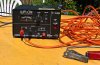
I have an old 'Transwest' brand Regulated Power Supply in good condition. It is a 12 volt (13.8V output) DC, 6 Amp rated at 50% Duty Cycle (?)
Input is 240 V 50Hz AC (I'm in Australia).
I was wondering if I can hook this directly to a depleted 12 Volt car battery to recharge it? I was going to continue googling, but you folk seem to have the knowledge, of which I am keen to learn.
Any advice would be greatly appreciated.
Thanks,
Griff
 
hi Griff,
I have used my bench PSU a number of times to charge a lead acid car battery, set to 13.8V it will be OK.
If you can squeeze 14.1V out of it, it will be OK.
E
 
Thanks Eric.
I assume I just need to keep an eye on it and check the charge every so often? BTW, nice avatar :).
 
G'day Mate,

Ideally, the supply has electronic current-limiting. If it does not, then there is a chance that you will overheat it or blow a fuse if you set it to a fixed voltage like 13.6V, and then connect it a depleted 12V Lead-Acid battery. The reason is that the battery will happily suck 20 to 30A when fed with a well regulated constant-voltage supply that is set to a higher-than-the-battery voltage.

I use a lab supply, which has two knobs; one to set the open-circuit voltage of the supply, the other to set the maximum current that it can deliver (its short-circuit current limit). This way, while the battery terminal voltage is below the supply's open-circuit voltage, the current is limited to a safe (for the supply) value. My settings for a car battery would be: 14.5Voc and 3Amax. It takes about 24hours to fully charge a 70Ah battery.

If your supply does not do over-current gracefully (it overheats or blows fuses), then you have two options:

The first is to measure the battery terminal voltage before connecting to the supply. Say it is 12.0V (mostly discharged). Set the supply to an open-circuit voltage of 12.0V, and then connect it to the battery. Now slowly increase the supply voltage until the supply current approaches 6A. Leave it that way until the current drops to say 3A, and then increase the supply voltage a bit more and so on. Stop charging after the supply voltage is 14.5V, and the current has dropped to less than 1A.

The second option is to go looking for a cement or wire-wound power resistor that is about 1Ω at about 15W. Hook it between the positive supply terminal and the positive battery post. It will get hot, but now you can start with the supply cranked up to 14V, and come back 15h to 30h later, and not hurt the supply or the battery.

ps: Spent 10years of my life down-under, as a "New Australian"
 
Last edited:
I suspect there's a lack of understanding in this thread, given the replies so far.

People seem to be imagining he has a variable lab power supply - from what he said in the original post I read it as he has a 'CB power supply', which is a fixed 12V (13.8V?) power supply, and no adjustable current limiting at all, in fact it may just have a fuse for over current protection. It's not really suitable for charging a battery, although running a wire out from the output of the bridge rectifier through a high wattage resistor would allow you to do it fairly crudely.
 
.....
running a wire out from the output of the bridge rectifier through a high wattage resistor would allow you to do it fairly crudely.
Actually, that's the way most cheap unregulated battery chargers work.
But instead of an external resistance, the transformer is designed with sufficient winding resistance to limit the current.
 
You can also use (two 12 Volt 60 Watt H4 car halogen bulbs in parrallel with each other) and put those those in series with your positive lead of the charging battery. I have done that with a fixed 8 Amp 13.8 Volts supply. When the battery has picked up enough charge over a 24 hour period the lamps are almost completely dim or can then be taken out of the circuit.
 
Actually, that's the way most cheap unregulated battery chargers work.
But instead of an external resistance, the transformer is designed with sufficient winding resistance to limit the current.

Yes I know, but as this is a regulated 13.8 volt supply then the DC voltage after the bridge rectifier is likely to be considerably higher than in a custom designed battery charger - so the current won't drop down in the same way as the battery is fully charged.
 
You can also use (two 12 Volt 60 Watt H4 car halogen bulbs in parrallel with each other) and put those those in series with your positive lead of the charging battery. I have done that with a fixed 8 Amp 13.8 Volts supply. When the battery has picked up enough charge over a 24 hour period the lamps are almost completely dim or can then be taken out of the circuit.

I've still got an old car fog light, which I've used over the years (decades!) to crudely charge car batteries - I can't even remember what I fed it from now?.
 
hi,
It is also possible to use 5 mtrs of 5A cable, between the PSU and battery as series limiter.
Loop resistance of 0.224R.
A002.gif
 
hi,
This is shot of the Bench PSU I used when charging a 12V car lead acid battery, cable is 10mtrs long to suit the house driveway.
The PSU is rated at 10Amp max,
E
 

Attachments

  • Picture 016.jpg
    Picture 016.jpg
    366.3 KB · Views: 308
The battery will gain a "floating charge voltage" of 13.6 to 13.8 very quickly and the charging will stop. 13.8v supply is insufficient. And I am in Australia too, so I know what I am talking about.
 
. . . . . . it should get him to about 14.2V. You have just shown he needs 2.45v per cell = 14.7v and then you need a few extra volts to push the 1 - 6 amps into the battery, so 14,2v is going to do NOTHING.
 
Maybe the "depleted car battery" is sulphated so much that it will not charge anyway?
 
. . . . . . it should get him to about 14.2V. You have just shown he needs 2.45v per cell = 14.7v and then you need a few extra volts to push the 1 - 6 amps into the battery, so 14,2v is going to do NOTHING.

What few extra volts past 14.7 are you referring to?
 
. . . . . . it should get him to about 14.2V. You have just shown he needs 2.45v per cell = 14.7v and then you need a few extra volts to push the 1 - 6 amps into the battery, so 14,2v is going to do NOTHING.
BTW since you are in Australia you OUGHT to be familiar with the temperature vs charge voltage relationship. But maybe this will help you...note the 14.22V Charge voltage for 30C ambient.
https://www.powerstream.com/SLA.htm
 
Hi
I have an old 'Transwest' 12 volt (13.8V output) DC, 6 Amp rated at 50% Duty Cycle (?) regulated Power Supply and it has a few wires broken off. Is there anybody with the circuit diagram so I can wire it up again?
Input is 240 V 50Hz AC (I'm in Australia).

Thanks
 
Status
Not open for further replies.

Latest threads

New Articles From Microcontroller Tips

Back
Top