fantabulous68
Member
Oh No...
i added the switches but when i run the code nothing appears on the screen.
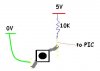
Am i supposed to configure the LCD to read??? At the moment its configured for write Only. The LCD is working when i COMMENT out //menu();. It displays infra red liquid level detector. However when i UNCOMMENT menu()...the lcd does not display anything. I connected switches to the PIC:
RC2 //HOME switch
RC3 //INCREASE switch
RC4 //DECREASE switch
RA4 //ENTERSETTINGS switch
The code compiles with menu uncommented out but it doesnt work in the circuit.
the new functions added (which might have problems i cant spot)are:
void init(void);
void read_input_sw(void);
void ShowDigits(unsigned char ,unsigned char );
unsigned char Combine(unsigned char , unsigned char );
int enter_settings(void);
void menu(void);
Here is the code:
i added the switches but when i run the code nothing appears on the screen.
Am i supposed to configure the LCD to read??? At the moment its configured for write Only. The LCD is working when i COMMENT out //menu();. It displays infra red liquid level detector. However when i UNCOMMENT menu()...the lcd does not display anything
. I connected switches to the PIC:RC2 //HOME switch
RC3 //INCREASE switch
RC4 //DECREASE switch
RA4 //ENTERSETTINGS switch
The code compiles with menu uncommented out but it doesnt work in the circuit.
the new functions added (which might have problems i cant spot)are:
void init(void);
void read_input_sw(void);
void ShowDigits(unsigned char ,unsigned char );
unsigned char Combine(unsigned char , unsigned char );
int enter_settings(void);
void menu(void);
Here is the code:
Code:
#include <pic.h>
#include "pic.h"
#include "delay.h"
#include "math.h"
#include <stdio.h>
#include <stdlib.h>

void FloatToStr(float , char[]);
void DelayMs(unsigned char);
void lcd_cmd(unsigned char);
void lcd_data(unsigned char);
void lcd_clear(void);
void lcd_puts(const char[]);
void lcd_goto_L1(void);
void lcd_goto_L2(void);
void lcd_cursor(unsigned char);
void lcd_init(void);
void init(void);
void read_input_sw(void);
void home_screen(void);
void ShowDigits(unsigned char ,unsigned char );
unsigned char Combine(unsigned char , unsigned char );
int enter_settings(void);
void menu(void);
void calc_distance(void);


#define LCD_RS RC0		//LCD RS pin
#define LCD_EN RC1		//LCD EN pin
#define LCD_STROBE()	LCD_EN = 1; asm("nop"); asm("nop"); LCD_EN = 0

unsigned char cm10;		//
unsigned char cm;		//
unsigned int math;		// used for voltage calculations
unsigned char NumDec;
unsigned char NumSep[2];

unsigned char i,j,k;
char temp[8];
int height=50, SensorPos=10;

char input_sw;
#define HOME_SW RC2				//HOME switch
#define INCREASE_SW RC3			//INCREASE switch
#define DECREASE_SW RC4			//DECREASE switch
#define ENTERSETTINGS_SW RA4	//ENTERSETTINGS switch


///////////////////////CONVERT FLOAT TO STRING///////////////////
// This function was taken from the CAVR library. It was modified slightly
// to suit our design.
void FloatToStr(float n, char str[])
{
float scale;
unsigned char d,f;
f=0;i=0;
if (n<0.0) {n=-n; str[f]='-'; f++;};
n=n+0.005;
scale=1.0;
while (n>=scale) {scale=scale*10.0; ++i;};
if (i==0) {str[f]='0'; f++;}
else
while (i--)
	  {
      scale=floor(0.5+scale/10.0);
      d=(unsigned char) (n/scale);
      str[f]=d+'0';
      n=n-scale*d;
	  f++;
      };

str[f]='.';
f++;
for (j=0;j<=1;j++) //2 decimal points
      {
      n=n*10.0;
      d=(unsigned char) n;
      str[f]=d+'0';
      n=n-d;
	  f++;
	  };
str[f]='\0';
}
///////////////////END CONVERT FLOAT TO STRING///////////////////

/////////////////////////////DELAY///////////////////////////////
void DelayMs(unsigned char cnt)
{
#if	XTAL_FREQ <= 2MHZ
	do {
		DelayUs(996);
	} while(--cnt);
#endif

#if    XTAL_FREQ > 2MHZ
	unsigned char	p;
	do {
		p = 4;
		do {
			DelayUs(250);
		} while(--p);
	} while(--cnt);
#endif
}

void DelayS(unsigned char cnt)
{
	for (j=0; j<(cnt*10); j++)
		DelayMs(100);
}
///////////////////////////DELAY END/////////////////////////////

//////////////////////////////LCD SETUP//////////////////////////
/* send a command to the LCD */
void lcd_cmd(unsigned char c)
{
	DelayMs(20); //wait for LCD to be ready
	LCD_RS = 0;	 //write instruction
	PORTB = (c & 0xF0); //load upper nibble on LCD data lines
	LCD_STROBE(); //send instruction to LCD
	PORTB = ((c << 4) & 0xF0); //load upper nibble on LCD data lines
	LCD_STROBE(); //send instruction to LCD
}

/* send data to the LCD */
void lcd_data(unsigned char c)
{
	DelayMs(20); //wait for LCD to be ready
	PORTB = 0x00;
	LCD_RS = 1; //write data
    PORTB |= (c & 0xF0); //load upper nibble on LCD data lines
	LCD_STROBE(); //send instruction to LCD
	PORTB &= 0x00; //load upper nibble on LCD data lines
	PORTB |= ( (c << 4) & 0xF0);
	LCD_STROBE(); //send instruction to LCD
}

/*Clear the LCD*/
void lcd_clear(void)
{
	lcd_cmd(0x01); //command to clear LCD
}

/*write a string of chars to the LCD*/
void lcd_puts(const char s[])
{
	j = -1;
	while(s[++j]!=('\0')) // send characters until null character reached
		lcd_data(s[j]);
}

/*go to beginning of line 1*/
void lcd_goto_L1(void)
{
	lcd_cmd(0b10000000); // command to go to line 1
}

/*go to beginning of line 2*/
void lcd_goto_L2(void)
{
	lcd_cmd(0b11000000); // command to go to line 2
}

/*move cursor "x" positions to the right*/
void lcd_cursor(unsigned char x)
{
	lcd_cmd(((x)&0x7F)|0x80);
}

/*initialise the LCD - put into 4 bit mode*/
void lcd_init(void)
{
	LCD_RS = 0;
	LCD_EN = 0;
	DelayMs(20); //wait for LCD startup
	lcd_cmd(0x28);	// 4-bit mode
	lcd_cmd(0x08);	// display off
	lcd_cmd(0x01);	// clear display
	lcd_cmd(0x0C);	// disp. on, cursor off, cursor blink off
	lcd_cmd(0x06);	// entry mode
	lcd_cmd(0x80);  // initialise DDRAM address to zero
}
//////////////////////////LCD SETUP END//////////////////////////


[COLOR="Red"]void init(void)[/COLOR]
{

    OSCCON|=0x60; //set fosc to 4Mhz
	TRISB=0x00;
	TRISC=0xFC;
    TRISA = 0b10000010; 	// RA7 high imp, RA3 is serial out,
	ANSEL=0x02;            //set RA1 as analog input for GP2 sensor
	ANSELH=0x00;
	lcd_init(); //call LCD initialisation


	/*
	OSCCON = 0x72;      	// internal osc, 8MHz

	PORTA = 0;
	TRISA = 0b10000010; 	// RA7 high imp, RA3 is serial out,
							// RA1 is ADC input measuring VR1
	PORTB = 0;
	WPUB = 1;
    RABPU = 0;

//	INTCON2 = 0;            // PORTB pullups ON
	TRISB = 0b00000000; 	// PORTB not used

	ADCON0 = 0b00000101;	// ADC ON, RA1 is ADC input
	ADCON1 = 0b01111101;	// AN1 is ADC input
//	ADCON2 = 0b10100010;	// right justify, 8Tad, 32Tosc

	T1CON = 0b00010001;     // TMR1 is ON, 1:2 prescale, =1MHz

//	T3CON = 0b00010001;     // TMR3 is ON, 1:2 prescale, =1MHz

	TRISC=0xFC;
	ANSEL=0x02;
	ANSELH=0x00;
	lcd_init();

	GIE=0;
	//PORTA = 0x00;*/


}

[COLOR="Red"]void read_input_sw(void)[/COLOR]
{
 char input_sw2;
 input_sw = ((HOME_SW*8)+(INCREASE_SW*4)+(DECREASE_SW*2)+(ENTERSETTINGS_SW*1)); //create a binary combination of the input switches
 if (input_sw != 0) //check if any of the switches are pressed
	{
	 DelayMs(20); //switch debouncing
	 input_sw2 = ((HOME_SW*8)+(INCREASE_SW*4)+(DECREASE_SW*2)+(ENTERSETTINGS_SW*1));
	 while (input_sw2 != 0) //if a switch is pressed wait for release
			{
			 input_sw2 = ((HOME_SW*8)+(INCREASE_SW*4)+(DECREASE_SW*2)+(ENTERSETTINGS_SW*1));
			 DelayMs(20); //switch debouncing
  			}
	 }
}


void home_screen(void)
{
	lcd_clear();
	lcd_goto_L1();
	lcd_puts("INFRARED LIQUID"); //home screen message (line 1)
	lcd_goto_L2();
	lcd_puts("LEVEL DETECTOR"); //home screen message (line 2)

}


//ShowDigits(3,5);
//	Displays 2 digit data to LCD
//---------------------------------------------
[COLOR="Red"]void ShowDigits(unsigned char var1,unsigned char var2)[/COLOR]{
	var1 += 0x30;
	var2 += 0x30;

	lcd_data(var1);
	lcd_data(var2);
}


//turn 2 digits from user into a single number (decimal) like
//Decimal 3 and 5 into 35(which is 0x23 in hex).

[COLOR="Red"]unsigned char Combine(unsigned char SinglePOS, unsigned char TenPOS)[/COLOR]{
   unsigned char wholeNum;
    wholeNum = SinglePOS + (TenPOS * 10);
    return wholeNum;
}

[COLOR="Red"]int enter_settings(void)[/COLOR]
{ int Var1=0;
  int Var2=9;
	do
    {	read_input_sw();
		switch (input_sw)
		{
			case 8: goto a;
			case 4: { Var1++;		//increase 1st digit
					  if (Var1>9)   //increasing 1st digit from 0 to 9 only-with each press
					      Var1=0;
					  NumSep[0]=Var1++;
					  break;
				    }
			case 2: { Var2--;		//decrease 2nd digit
					  if (Var2<0)	//decreasing 2nd digit from 9 to 0 only-with each press
						  Var2=9;
					  NumSep[1]=Var2;
					  break;
				    }
			default : goto a; //should any abnormalties occur
		}

	    	ShowDigits(NumSep[0],NumSep[1]);
	 }
	while (input_sw==1);


     NumDec = Combine(NumSep[0],NumSep[1]);
   	 return NumDec;

a:
	return;
}

[COLOR="Red"]void menu(void)[/COLOR]
{
	read_input_sw();
	while ((input_sw != 8)&(input_sw != 1))  //Wait for Home or enter/settings
	{
		lcd_clear();
		lcd_goto_L1();
		lcd_puts(" ENTER/SETTINGS ");
		DelayS(1);
		lcd_clear();
		ShowDigits(NumSep[0],NumSep[1]);
		lcd_clear();
		lcd_goto_L1();
		lcd_puts(" ENTER HEIGHT ");
		height=enter_settings();
		lcd_clear();
		lcd_goto_L1();
		lcd_puts(" ENTER SENSOR POSITION ");
		SensorPos=enter_settings();

	}
}


void calc_distance(void)
{
	// from the transeiver datasheet the analog voltage is
	// the inverse of distance, so distance can be calculated
	// d = (1 / volts) then just scaled to suit the transeiver

	// load ADC value in 16bit math var
	math = ADRESH;
	math = (math * 256);
	math += ADRESL;

	// now invert it; (1 / volts) use (6050 / volts) for scaling
	math = (6050 / math);
	if(math >= 2) math -=2;		// fix linear error (-2)
	if(math > 99) math = 99;	// max limit at 99cm

	// convert from 0-99 to 2 decimal digits, 0-99cm
	cm10=0;
	while(math >= 10)
	{
		cm10++;
		math -= 10;
	}
	cm = math;
}


void main(void)
{
	init();	// initialise I/O ports, LCD
	while (1)
	{
	//menu();
	home_screen();

	}

}
Attachments
Last edited:
