Continue to Site

Welcome to our site!

Electro Tech is an online community (with over 170,000 members) who enjoy talking about and building electronic circuits, projects and gadgets. To participate you need to register. Registration is free. Click here to register now.

  • Welcome to our site! Electro Tech is an online community (with over 170,000 members) who enjoy talking about and building electronic circuits, projects and gadgets. To participate you need to register. Registration is free. Click here to register now.

Urgent help needed regarding CT ratio???

Status
Not open for further replies.

tkvenki

New Member
Hi all.

I'am not able to get the CT ratio to interface the CT to ade7754 evaluation board.

In some diagrams they have ashown a 1:1800 CT....And they have connected the "1800" part to the evaluation board. But i doubt connecting the CT like this.

Please resolve this issue...I looked in the datasheets but could not find enough information.

Thanking you
Venkatesh
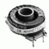
 
By "CT" I assume that you mean Current Transformer.

A CT with 1:1800 turns ratio, will convert a current of 1800amps to 1 amp.

The 1800 amps is usually a single wire passing through the core of the transformer, the 1 amp comes from a 1800 turn secondary winding which must be terminated with a suitable load resistor, say 1 ohm, which will give 1 volt when 1800 amps is flowing in the primary wire of the CT.

JimB
 
Thanks a lot

Dear Jim,

Thanks for the reply.....
So the evaluation board is capable of handling 1A current am i right??

But my problem is...The analog devices have provided one calibration software which will instruct us to set the current to 10A...

And beleive me....nowhere analog devices have mentioned that what is the CT ratio we must use ...what is the current burden of the evaluation board.

I FEAR that my board may get damaged if i will give 10A.
I have sent query regarding this to analog devices and have not got any reply yet.


I will be thankful to you if you can help me.


Thanks for the reply
Venkatesh T.K
 
Venktash

I am sorry but I have no information about your development board.
You asked a question about current transformers, I answered using some easy numbers to help the explanation.

I do not know the ratings or limits of your system.

JimB
 
Hi tkvenki,

It is difficult to see where your problem lies.

In some diagrams they have ashown a 1:1800 CT....And they have
connected the "1800" part to the evaluation board. But i doubt
connecting the CT like this.

I assume that when you say a CT you mean a current transformer.
I further assume that by current transformer you mean like this:

**broken link removed**

This unit is intended to surround one of the current carrying
conductors from the primary current source. As you can see there are
only two connections on this unit. These two connections are for the
analogue indicators.

It is toroidally wound with many many turns, and a fairly high internal
impedance. It is intended to give a (relative) reading of current
at its output terminals.
This output current is intended to be consistent whether one or many
analogue devices are placed in series as a load across its terminals.
The load across its terminals is not intended to alter the current
reading that it puts out ... unless the output impedance gets
abnormally high, such as an open circuit.

It achieves this by having a very high available output voltage, and also
a fairly high internal resistance. The output voltage is normally kept low
because of the analogue devices that it is running.
The result is that many analogue devices, usually meters, can be put
in series, without affecting their readings (very much).

The down side is that one must take special care to avoid an open
circuit in the indicator line, because this can cause very high
voltages to appear in that circuit.
Such high voltages are not usually expected in instrument panels,
and can be lethal, or cause damage to insulation or other parts of
the instrument panel.

As the current feeding these devices is limited it is permissable to
short circuit the output terminals without worrying, but an open
circuit is only alright if the primary current carrying conductor
cannot carry any current, because very high voltages can occur.

This is an old fashioned set-up, and may cause confusion for some
one who is not familiar with the way that the meters are set up,
sometimes with long runs of cabling, which don't seem to have their
resistance taken into account at first sight.

Google has no definition for an evaluation board, so i can't really
help much there.

But i will try to help with the calibration.
The CTs and the meters usually come as a set, but they don't have to.
I assume the analogue indicators are meters.
If the meters are for use with a CT then there should be an indication
around FSD of the CT output current, which should be marked on the CT.


On this meter there is a little tiny '5' marked discretely on the
outer edge, just by the '100' mark.
That is because this meter is for a CT output of 5 Amps at its
intended high reading, when its primary current carrying conductor is
passing 100 Amperes.
Accordingly the meter or meters to be used with this CT would be bench
set to read in that position with 5 Amperes going through the meter.
This would be adjusted by shunts within the meter itself, not
externally. Externally the meters would just be wired in series with
each other, across the CT terminals. Some meters may be quite a way
off, and the instrument mechanic should be made aware of the dangers
and should take precautions as necessary.

So:
The meters are wired in series, the current through each is the same.
( for the given CT )

I hope this helps, but it is difficult to follow your request.

Best of luck with your arrangement, John :)
 

Attachments

  • currenttransformer.gif
    currenttransformer.gif
    14.5 KB · Views: 542
  • meter_242.jpg
    meter_242.jpg
    60.7 KB · Views: 545
well i sort of got the pics to go in the text,
.............. now i dunno how to get rid of the
extra pics at the bottom of the post ........

John :)
 
Re: The problem

tkvenki said:
Dear all...

Thanks for the responses.
I had posted a query in the following link:

https://www.electro-tech-online.com/threads/radio-ics-these-things-are-tiny.19039/

I have posted a link to the evalation board document.
Also i have sent a screen-shot which specifies my problem.

The calibration software(the screenshot) says to set the current to 10A.
But i doubt that my eval-board will withstand 10A.

Kindly help me out.

Thanking you
Venkatesh T.K

Try reading the previous replies! - Russlk suggested earlier that the 10A is the current in the PRIMARY of the current transformer. I was under the impression that this design was being done for a company?, or at least as part of a college course?, how do you come to be involved in it? - no disrespect, but you appear to have very little electronics knowledge?.
 
Hi tkvenki,

Ive looked through that PDF,
and your other post.

It actually says:

'Please set Voltage input on Phase A at 220V
and Current input on Phase A at 10.000A with a Power factor = 1'

My interpretation of this is that you are to arrange for the voltage
on Phase A (typically the red phase) to be 220 volts, and that you
are also to arrange for the current through that phase to be 10 Amps.

(when bench setting these, they are not usually done at the same time,
the ten amps(AC) may be set using a feed from a small local supply,
with a suitable wire passed through the CT, then the 220 volt setting
can be done separately, before the units are assembled into place.)

The ten Amps in the main current carrying conductor, looks to me as
though it would correspond to one half of a volt being fed to the
'ADE-7754'

I am pretty sure that the ten amps is only in the main conductor, and
not in the 'ADE-7754' or any of the small wiring associated with it.

I am not familiar with this device, but i have looked at the partial
diagrams on thr PDF, but only briefly.
I feel that the resistors shown in series with the CT output are a
good bit higher than i would expect, unless the CT being used is
limited to quite a low current.

There is a section in that PDF which describes the caution which
should be exercised to ensure that the CT output should be 'loaded'
at any time that its in service.
I should try to stress that these voltages are unusually high, they
do not come from the 220 volt supply, they come from a 'step-up'
voltage transformer, although it is small, the voltages can be lethal
from this unit, if its load is accidentally removed.

I don't feel that the PDF makes enough of a big deal about this.

Anyone working on equipment using this type of device should be made
aware of the dangers involved, and take due care.

This is not the sort of device that would necessarily be expected by
an instrument technician when dealing with electronic equipment.

So,
I think you 'set' the indication at ten amps,
on the 'ADE=7754',
when you decide that the main current on Phase A is at ten amps,
although the 'ADE=7754' is only getting about half a volt.

I hope this helps, best of luck with this project, John :)
 
Status
Not open for further replies.

Latest threads

New Articles From Microcontroller Tips

Back
Top