Continue to Site

Welcome to our site!

Electro Tech is an online community (with over 170,000 members) who enjoy talking about and building electronic circuits, projects and gadgets. To participate you need to register. Registration is free. Click here to register now.

  • Welcome to our site! Electro Tech is an online community (with over 170,000 members) who enjoy talking about and building electronic circuits, projects and gadgets. To participate you need to register. Registration is free. Click here to register now.

Up/Down JK Flip Flop Counter

Status
Not open for further replies.

lambertlai

New Member
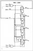
My project is showing the Car Park Slot from 99 to 00. So i just design the 1st stage of the circuit first.

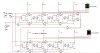
I was design the Up/Down JK flip flop using the logic gates, but when the decimal until 9 it will continues to A,B,C,D,E,F then back to 0.

The problem was:
1. i need from 9 to 0 only or 0 to 9 only, the A until F NO NEED to show.

2. Because have TWO digit need to showing so how should i connect it from one digit to two digit. Which mean that 99, 98, 97, 96, 95......until 00.Or 00, 01, 04,,06,,56 and so on
 

Attachments

  • JK up down ff01111.JPG
    JK up down ff01111.JPG
    58 KB · Views: 4,406
Last edited:
This is how a decade counter (0 thru 9 count) is implemented using J-K Flip Flops inside the 7490 IC. It may help to determine how to get your Flip Flops connected correctly. It does not count down, but you can see how QD gets reset to zero on the next clock pulse after the "9" count is reached.
 

Attachments

  • Drawing1.jpg
    Drawing1.jpg
    87.8 KB · Views: 2,302
Last edited:
Your counters will have to be seriously modified to do what you want. For each of the two counters you need to decode the "9" output to prevent the Qb and Qc flip-flops from toggling only during the up-count while allowing the Qa and Qd flops to toggle and decode the "0" output to prevent the Qb and Qc flip-flops from toggling only during the down-count while allowing the Qa and Qd flops to toggle. Because of the way your counters work, that is not trivial, and requires a handful of added gates and some existing gates need to change to have more inputs.

Cascading the two counters is also not trivial. The clock for the counters needs to be gated with the decoded "9" and decoded "0" depending on which direction you are counting.

If you must go with individual flip-flops and gates, see how the flip-flops are connected inside the 74HC190 (up/down decade counter) IC and you will see how extensive the modification needs to be.
 
It's quite easy to construct a simple counter that resets when bits out reaches 1010b AND up/down input is hig, and reset/set the apropriate toggles when output os 0000b AND the up/down input is low.

Image here that might work.
 
Last edited:
yup, Thanks a lot yours help.....
Now i tried another way to design the gates. It was successful.
Next i need connect 2 digit together which mean 99 or 00.
Thanks
**broken link removed**
 
Status
Not open for further replies.

New Articles From Microcontroller Tips

Back
Top