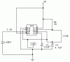
i've already did the 555timer as a pulser, but in circuit maker... it cannot simulated capacitors and other
components... but i did choose the PROBE to check the pulse output of 555 timer connected to the wire
of the CPU, then the display add up as i click on the wire, does it mean that the circuit already works
in actual circuit? the display does not run beacause, the circuit maker, cant simulate some
of the analog components, but the circuit really works, even in actual?
is this true?
big thanks to all of you, i'm hoping that i'm on th 90% of this circuit ( but in actual its 0% )