Hi all,
Just wanting to run this by you.
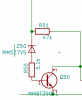
I've a simple voltage based switch which turns off a mosfet. The fet is rated to 60V with 20V gate. The transistor is the common MMBT3904 rated to 40v.
I'm currently testing with a voltage up to 20v.
It's working correctly, turning off the fet around the 8v mark, but not for long. After some time the transistor creates a short between c+e. Sometimes I can clear it by shorting base to ground but eventually it makes no difference.
I can't see a problem. Even at 10v over the zener the resistor is dissipating 0.01W. The C+E current is much less.
Any ideas?
Andrew
Just wanting to run this by you.
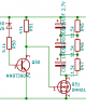
I've a simple voltage based switch which turns off a mosfet. The fet is rated to 60V with 20V gate. The transistor is the common MMBT3904 rated to 40v.
I'm currently testing with a voltage up to 20v.
It's working correctly, turning off the fet around the 8v mark, but not for long. After some time the transistor creates a short between c+e. Sometimes I can clear it by shorting base to ground but eventually it makes no difference.
I can't see a problem. Even at 10v over the zener the resistor is dissipating 0.01W. The C+E current is much less.
Any ideas?
Andrew