Continue to Site

Welcome to our site!

Electro Tech is an online community (with over 170,000 members) who enjoy talking about and building electronic circuits, projects and gadgets. To participate you need to register. Registration is free. Click here to register now.

  • Welcome to our site! Electro Tech is an online community (with over 170,000 members) who enjoy talking about and building electronic circuits, projects and gadgets. To participate you need to register. Registration is free. Click here to register now.

Unexplained changes in circuit output

Status
Not open for further replies.
Morning all,

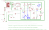
OK so I finally get to use the fridge thermostat I made but it is not behaving as I would have expected, nor is it behaving as it did in trials. Let me explain myself;

Before we left on our camping trip the circuit was tested and debugged throught help on this forum and through physical trials on my spare home fridge. Two days before leaving on our trip I allowed the fridge to cooldown and it did so as expected. It was set for a range to break relay contact at 3 deg C and make contact at about 4.5 deg C i.e.

The fridge was loaded the evening prior to departure (with already cold contents). When we got to the camp site the fridge would not cool to below 8 deg C, it was cycling as if the set point had shifted out to 8 deg C, I had not altered the setting.

Confused I reset the set point over the next 12 hours back to the 3 to 4.5 deg C range. The unit perfomed as expected for the next 48 hours. Woke up this morning and the fridge was at 0.7 C deg and is cycling around that range? Again the set point appears to have moved, only this time in the opposite direction?

OK so the ambient is much lower this morning but that should make no difference, all it means is that the cooling is more efficient, the thermistor resistance should still trigger the circuit at the same point for the same given temperature / set point. Ambient yesterday was 38.1 deg C today it is 20.2 deg C surely this could not cause a large variation in the resistance of resistors?

It is almost as if there is factor causing the resistance somewhere in the circuit to alter, would that make any sense? Would the solder joint on the thermistor located in the fridge need to be specially made, care taken etc due to the lower operating temperature?


Any thoughts.

Regards
Andrew
 
hi Andrew.
I would suggest you measure some of the voltage points in the circuit, before and after a major change in the 'unwanted' change in operating point.

The points I would measure are the +V supply rail, the output pin of the 741 and the actual sensor output voltage.

Lets know what you find.
 
Hi Eric,

Thanks, we are talking in the ON state obviously. It is kind of difficult to get to but will see what can be done. At the moment left a miniture screwdriver bit in the trimpot, I stick my hand in find the bit and adjust.

OK not as bad as difficult as I thought;

Relay off
0V to Pin 6 = 11.3V
0V to +12V = 11.8V
0v to Sensor = 5.7V

Relay on and set for min temp of 3 deg C
0V to Pin 6 = 2.0V
0V to +12V = 11.8V
0v to Sensor = 5.6V

Will have to wait until the circuit shifts again, if it does that is.

Can you read anything into this?

Cheers
Andrew
 
Will have to wait until the circuit shifts again, if it does that is.

Can you read anything into this?

Cheers
Andrew

Hi,
I will wait for the next set of readings when the tempr has 'jumped'

The forum site is playing up today!
 
Hi Eric,

looks like the set point has drifted up by 2 deg C. Observations are that the supply stays unaltered at 11.8V the on / off voltage at pin 6 is also unaltered at 2.0V / 11.3V respectively. The only voltage that alters is the one measured at the thermistors ( which one would expect as it is temperture dependent). Instead of going off at 3 deg C it has just switched off at 5.4 deg C??? Voltage at the thermistor from ground = 5.8V.

By the way the ambient has stayed the same as it was yesterday so the effect of temperature on resistance is obviously very small, but you already knew that!

The hysteresis stays roughly the same but the set point appears to drift. The set point is a function of the the offboard 5k pot and the 10k onboard trim pot.

I am trying to set the minimum temp. According to the writeup this is done by setting the offboard 5k pot to max and then by setting the onboard trimpot, which is in series, to the min temp required. This is like a safety measure as it stop you setting the offboard pot to a temperature that may freeze the fridge. I just cant get the temperature to stay the same.

Are pot's inaccurate? Are they more inaccurate at their exteme settings?

Still confused, any thought from your side?

Cheers
Andrew
 
Hi again,

So much for my comment on the hysteresis being about right. The unit switched off at 5.4 dec c and 10min later switched on at 5.4 deg C???


Andrew
 
Hi again,

So much for my comment on the hysteresis being about right. The unit switched off at 5.4 dec c and 10min later switched on at 5.4 deg C???


Andrew

hi,
Do you have a 'better' OPA than the 741 you could pop into the circuit.?

What OPA's do you have on the shelf.?
Where did you get the circuit.
 
Hi Eric,

the circuit comes from Craig's Thermostat Circuits and the power supply was added by myself along with recommendations from members who chirped in on the caps etc. I also needed to change the resistors on the comparitor to line up with the range of the thermistor I am using, think you helped on that.

Where I am don't have access to any OPA's, you did point out from the begining that the 741 is somewhat of a relic. Can you recommend a OPA that could directly plug in? When I get back will get some and resume the tests. For now think we are snookered and are best waiting until a decent OPA is inserted.

Could a poor solder joint be responsible for this erratic performance or is that a long shot?

Thanks for the time
Andrew
 
Hi Blueroomelectronics,

so much I have realised. Unfortunately I am a build by numbers person so I take circuits from the net and hope to hell that they work. It is very difficult for me to understand what is good and what is not, therefore I rely heavily on forum members.

The LM311 has different pinouts so the circuit will need redraw, not the end of the world.

Would that fix my problem Blueroomelectronics?

Cheers
Andrew
 
How long is the wiring? You may have oscillation.

How are you measuring temperature? The voltage across the thermistor is changed by the hysteresis. To get an accurate reading you need to measure its resistance with it disconnected from the circuit (or use an independent sensor).

- The thermistor in particular should at least be on twisted pair, preferably shielded.
- Similarly, the external pot should be as close as possible to the board, and have its case (if it's metal) connected to circuit common (pot. center terminal).
- Be sure C2 is in place. It could help if you added another C2 across the V+ and V- pins of the comparator.

Another piece of good news about the LM311 comparator is that Q2 is included if your relay is less than 50mA (generic small 12V relays use about 35-45 mA.)
 
OK could have a problem here,

Pot on ±300mm wire, not shielded nor is the metal case earthed.
Thermistor on ±1000mm wire not twisted nor shielded.

Cheers
Andrew

Forgot to mention, the thermistor is used as one leg of the of the comparitor, when the resistance goes either high or low the circuit activates or deactivates.
 
Last edited:
Twisted doesn't mean strangled; just have to be kept tightly together over their length.

Shielded is best, of course.

Earth on pot not really important unless it is touching something else (or a person). But it's too easy to do.
 
Hi,

the wire I used consists of three wires side by side in a flat arrangement (like ribbon wire) which is enclosed in a PTFE sheath. Could this lead to capacitive issues?

At the time could not find a wire that would cope with 3-5 deg C continuously.

Cheers
Andrew
 
Hi,

could internal heating of the thermistor be a problem?

To find out thought I would try teach myself some theory. Between the + and - rail we have a 15k and a 5k thermistor in series.

Current through the resistors
I = 12V/(15k+5k) = 0.6mA

Volt drop across the 5k thermistor
V = 0.6mA*5k = 3V

Power dissipated in the thermistor
P = ((0.6mA)^2)*5k = 1.8mW

If the above is correct would 1.8mW be material?

Cheers
Andrew
 
Hi,

the wire I used consists of three wires side by side in a flat arrangement (like ribbon wire) which is enclosed in a PTFE sheath. Could this lead to capacitive issues?

At the time could not find a wire that would cope with 3-5 deg C continuously.

Cheers
Andrew

hi,
Is this the circuit that you are using.?
Whats the resistance of the thermistor at room tempr.?
 

Attachments

  • Circuit1.png
    Circuit1.png
    16.6 KB · Views: 150
Hi Eric,

Yes it is the circuit BUT for R4= 10k and R3 - 10k. I may have confused you. I started the new thread as the old one called "hysteresis" was about taking my prototype circuit and getting it to work with a 12V car relay which works now. This dropped R3 and reduced R4 to 1k. So the circuit as you show it is actually for the 12V car relay adjustment.

The circuit in use at the moment is identical to the one I posted above and includes R3 @ 10k and R4 @ 10k. The thermistor is 10k @ 25 deg C (it is in the order of 5k at the temperatures of a fridge hence 5k in my calcs.)

Does that make any sense.

Cheers
Andrew
 
Last edited:
That type wire shouldn't be a problem at those distances.

Self heating is definitely of interest. See if you can find out the thermal resistance of your part. I glanced at a catalog and found one with a thermal constant of 1 degree per milliwatt.
 
Hi Eric,

Yes it is the circuit BUT for R4= 10k and R3 - 10k. I may have confused you. I started the new thread as the old one called "hysteresis" was about taking my prototype circuit and getting it to work with a 12V car relay which works now. This dropped R3 and reduced R4 to 1k. So the circuit as you show it is actually for the 12V car relay adjustment.

The circuit in use at the moment is identical to the one I posted above and includes R3 @ 10k and R4 @ 10k. The thermistor is 10k @ 25 deg C (it is in the order of 5k at the temperatures of a fridge hence 5k in my calcs.)

Does that make any sense.

Cheers
Andrew

hi,
Ok, I'll run a tempr simulation using a 'standard' thermistor.
Do you have the type number of the actual thermistor.?
 

Attachments

  • Circuit1.png
    Circuit1.png
    16.8 KB · Views: 198
Status
Not open for further replies.

Latest threads

New Articles From Microcontroller Tips

Back
Top