Continue to Site

Welcome to our site!

Electro Tech is an online community (with over 170,000 members) who enjoy talking about and building electronic circuits, projects and gadgets. To participate you need to register. Registration is free. Click here to register now.

  • Welcome to our site! Electro Tech is an online community (with over 170,000 members) who enjoy talking about and building electronic circuits, projects and gadgets. To participate you need to register. Registration is free. Click here to register now.

Understanding two Multivibrator models

Status
Not open for further replies.

Alex_bam

New Member
Hello,
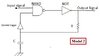
I simulated the two multivibrator models in CMOS technology using the cadence tool. I was expecting the model 2 with Schmitt trigger(ST) will show robustness in PVT (Process Voltage temperature) analysis as compared to model 1 due to ST. But this was not the case both the Models shows the same response to PVT variation analysis means their outputs were stable under varying PVT conditions. Could anyone address my queries:
  1. Is Schmitt trigger in Model 2 having an edge over model 1?
Thanks.
 

Attachments

  • Model 1.jpg
    Model 1.jpg
    12.4 KB · Views: 242
  • Model 2.jpg
    Model 2.jpg
    15.3 KB · Views: 233
Last edited:
Can you show the timing diagram of what you're seeing? Also values for the R and C. That would make it easier to interpret what's going on.
 
Can you show the timing diagram of what you're seeing? Also values for the R and C. That would make it easier to interpret what's going on.
I chose R=15K and c= 1pF in both models. Moreover, the timing diagram of both models is almost the same under PVT analysis.

I have attached one result of Temperature variation from -40 to 50 C.
 

Attachments

  • Capture.PNG
    Capture.PNG
    74.5 KB · Views: 241
Last edited:
part of PVT is "process"..... what actual components (or models for them) are you using for the logic? if you are using the "generic" model, it might not have any temperature coefficients in the model... if instead you use TTL or CMOS models based on 74xx or 40xx devices, then you will likely see variations due to temperature. and you may get a surprise with the component values you chose because input/output capacitances of real ICs will swamp the 1pf in the schematic and you won't get the frequency or behavior you expect.
 
Status
Not open for further replies.

Latest threads

New Articles From Microcontroller Tips

Back
Top