KartikVepa
New Member
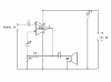
Hi, I want to start making circuits, but I'm finding the circuit diagrams to be very confusing. For example, in the audio amplifier attached, I don't know what the upside down triangles are, I don't know where the - of the audio input goes, where the - of the voltage input goes, or what I connect the - of the speaker to. If someone could explain the diagram to me, that would be awesome, thanks. **broken link removed**