Continue to Site

Welcome to our site!

Electro Tech is an online community (with over 170,000 members) who enjoy talking about and building electronic circuits, projects and gadgets. To participate you need to register. Registration is free. Click here to register now.

  • Welcome to our site! Electro Tech is an online community (with over 170,000 members) who enjoy talking about and building electronic circuits, projects and gadgets. To participate you need to register. Registration is free. Click here to register now.

Unable to find out problem

Status
Not open for further replies.

Nathaniyelu

New Member
Hi everyone,
This is Nathaniyelu from India..
Iam working as a trainee engineer..
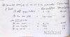
They gave me this circuit to find out the problem...
This is a 20years old circuit..
All I.cs are 14 pin..
With this device they will test glass..
Whether the glass is properly passing light or not..
One side(receiver photo diode)and other side of the glass a transmitter(IR Led) they Will put and check the dc ammeter reading..
If the reading is 50mic.Amp..glass is o.k..
If we put opaque material between Rx and Tx..reading should be 100mic.Amp..(full deflection)..
Please help me out..
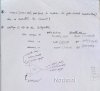
Especially the receiver circuit is o.k..?
And connections also..
Thanks in advance..
 
Are you saying the circuit doesn't work? What is it not doing? What does the output read?
The amplifier on the left - is pin 10 connected to anything beyond R5? Did you verify +Vcc is +12 volts and steady?
You should always identify what the problem is exactly, and 1st always verify that you have clean power.
Many problems can be seen if you know where to look - did you make a careful visual inspection?
Need much more info and perhaps pictures.
 
if the ammeter is used to measure translucence, then it should be in the receiver circuit.
i would say at the output of the 741, which doesnt seem to go anywhere, except the gain loop.

maybe the receiver op amp out is coupled to a thresh hold indicator. then pot on the transmitter is adjusted until receiver shows logic HI, resulting ammeter reading gives relationship of opacity.
i think this may be more plausible, given the higher reading for the less clear glass.
 
Last edited:
Thank you very much for your kind response..Rich and oemcar..
The circuit is working but functionality not there..
I have replaced All the I.cs except ic3(741)precision rectifier..
Later found that by varying both gain control and zero control dc ammeter reading varying from 80-100mic.Amp.
After searching on Google..
I came to know that the receiver circuit is oscillator circuit and I removed that out put wire(blue)and reference voltage (6.04V)wire(black)and power up the circuit..found 4v~ac is coming..!..
Now I connected the blue wire at the end of .033uf capacitor and simultaneously replaced the reference voltage wire as before..miraculously photo diode is responding to room light..!!..
And also met one of the three conditions..
Now that the transmitter section is not working..found IR Led(1.anode connected to +vcc+12. 2.cathode connected to the collector terminal of T1 transistor there iam getting around 10Vdc..)was shorted even after replacing new diode also no light is coming..
Lm311ic output will be a square wave..
If you got any ideas please give..
 
I came to know that the receiver circuit is oscillator circuit and I removed that out put wire(blue)and reference voltage (6.04V)wire(black)and power up the circuit..found 4v~ac is coming..!..

thats because the circuit is in open loop

Now I connected the blue wire at the end of .033uf capacitor and simultaneously replaced the reference voltage wire as before..miraculously photo diode is responding to room light..!!..

now you have a unity gain follower, which will control the open oscillation


And also met one of the three conditions..
Now that the transmitter section is not working..found IR Led(1.anode connected to +vcc+12. 2.cathode connected to the collector terminal of T1 transistor there iam getting around 10Vdc..)was shorted even after replacing new diode also no light is coming..
Lm311ic output will be a square wave..

hmmm... processing- lol

If you got any ideas please give..

imo- this circuit is a test since the desired results could easily be attained with a simple linear equivalent
 
Last edited:
The Comparator is generating square wave..but it was disappearing at the collector terminal of the T-2 transistor..
Later found that the collector lead was dry soldered..after soldering..,ammeter reading went to zero!..Now it's not responding to gain and zero control..
And also reference voltage dropped to 3.58V from 6.16V..
2N3819,T1, T2,and zener also working perfectly..
One thing I have found that the square wave(generated by the comparator)is turning to triangular shape at 360ohm resistor(see at T1 emitter end)..
I don't know whether it is normal or abnormal...
Please give some suggestions..
Thanks again for your help..
 
This is my understanding of how the right hand end of the circuit (The square wave constant current LED driver.) should work. The 2N3819 and it's source resistor provide a crude constant current source for the zener diode. I EXPECTED the zener to be about 6 volts to provide about a half the 12 volts supply voltage as a reference voltage for the op amps on the left hand side of the circuit and also a reference voltage for the constant current LED driver T1 and it's emitter resistor. When I looked at the data sheet for the 1N4753 I saw it was a 36 volt zener. I think the wrong zener diode has been fitted. With a 36 volt zener fitted then I would expect the voltage on the top of the zener to be close to 12 volts. Something is drawing too much current. It could be C3 or c5 being leaky or more likely T1 being faulty. I suggest disconnecting the base of T1 and checking if the voltage on the top of the zener rises. I am almost certain that you will need to replace the 1N4753 zener with one around 6 volts. When the circuit is working correctly I would expect to see square wave on the collector of T2 with a low level of about 0.2 volts and a high level of about 10 volts. (This is assuming the zener is regulating at 6 volts.)

Les.
 
Thanks a lot for your advice..
I have changed those capacitors(c3 andc5)..Now I'm getting 6.05v without any loss..and also met second condition..
But the problem is my circuit is not able to distinguish the clear glass and erroded glass..
Especially for erroded glass..
Ammeter reading should be 50mic.Amp..but it is showing the reading same as clear glass...
At the gain control trimmer a 390k resistor is there in series with(see in the circuit)..Now I'm changing that resistor values and checking..but not able to get that reading..

Please note:

1.I wrongly mentioned that zener..
Actual-1N4735..

2.recommended supply is 18v..
After fixing the new capacitors I increased the supply to 17v only suddenly I got 6.05v..may be supply not sufficient to charge the capacitors..!
3.earlier I got good result of gain control with 8pin I.c s..which I soldered back side of the pcb..
But one day that integrator I.c two wire s (out put and vcc)found shorted..!!I immediately resoldered properly..
But I don't know still any problem exists due to that short circuit..
4.earlier even though if I had removed three ics from the pcb..I was able to control gain!!..Now I can't..

5.remember now I'm able to get gain control half of the scale..means 50-100mic amp,if I put an opaque material between transmitter and receiver...


Please give some suggestions..
How get that third condition...

Thanks in advance..
 
The 1N4735 is a 6.2 volt zener which is correct if the supply voltage is about 12 volts. Did you do anything to identify if the reference voltage from the zener was being loaded by the base of T1 or the wire /track going to bias the op amps IC2 and IC3 ? If the unit was working originally with a 12 volt supply why have you increased it to 17 volts ? Your fault finding technique does not seem very logical. I think you should first make sure that the IR led is working and is giving the required output signal. I would expect to see a square wave of about 1.5 volts amplitude across the IR LED. Also if you have a two channel oscilloscope that has the invert and add function look at the waveform across the 360 ohm resistor R1. I would expect to see a square wave with about a 6 volt peak to peak amplitude.

Les.
 
No bro,
Prescribed power supply for the unit is maximum 18volts..
Before I started..someone(5-6members) had already done something on this unit..
That's why I didn't put 18volts..because of some wrong connections..

Any how I believe..now the unit is working properly with 80% accurate..
I already attached two photo's..Please see and give me advice..only one condition..iam not able to get..
I.e the unit is not showing any difference between a clear glass and an erroded glass..:rolleyes:
Thank you once again..:):)
 
I think the gain setting of the integrator stage is set too high. I suggest setting the integrator gain to its lowest setting to start with. (The potentiometer adjusted to end that gives the lowest resistance between pin 1 and pin 3. Then with opaque material between the IR source and the detector adjust the zero c0ntrol so the meter reading is 100 uA. Now slowly move the opaque material out of the path and watch the meter reading at the same time. The meter should only reach a zero reading when the material is almost completely removed. If the meter reaches zero while the path is still partly obscured The gain is still too high. If this happens you could try adjusting the zero setting (With the path clear.) until the meter just moves off the zero reading. If you can get this to happen then see what the readings are with clear glass and with faulty glass sample.

Les.
 
Thanks for your advice..
I have tried what you said..but found no control of zero and gain...
Especially for erroded glass and clear glass, i have found that excess 34uAmp is coming at the ammeter that too not decreasing to zero..!!
We need:
0uAmp for clear glass..
50uAmp for erroded glass...
At that time only calibration test can be done..
How to reduce this current..?
I think I would like to do something at receiver circuit...
Please give some suggestions..
I have attached readings..please go through..:):rolleyes:.
I don't have any service manual of this unit.
Thank you once again for your kind advice..
 

Attachments

  • Fotor_146169565256734.jpg
    Fotor_146169565256734.jpg
    1.2 MB · Views: 243
  • Fotor_146169578302212.jpg
    Fotor_146169578302212.jpg
    613.2 KB · Views: 303
Last edited:
I think the input preamplifier is being overdriven and is limiting. (Or a component in the feedback circuit has changed value making the gain higher than it is designed to be.) Things to check. Has the IR transmitter diode been replaced with one that gives more output than the original or is it being driven with too high a current ? You never said what happened when I suggested disconnecting the base of the driver transistor when you were looking for the low reference voltage from the zener diode. You just replaced two capacitors and increased the supply voltage without why you did either.
Has the IR detector been changed to a more sensitive one ? Has the optical path been changed. (I.E distance between source and detector, filters or lenses been changed.) I would aim to get a 50% reduction in output from the active rectifier when your test sample is placed in the path.

Les.
 
Yes..
The IR Led is giving more light..
Earlier I was using photo transistor and a different wavelength IR Led..!!now I have changed both and put
A proper matching pair..and also put as away as possible from the testing glass..now the reading s are coming nearest calibration values...
We are waiting for final inspection..
If it passes.. the unit will be finalized..
Thanks a lot for your kind advice..
I have few doubts regarding this circuit.:rolleyes::stop:
1.receiver circuit is an amplifier/ oscillator circuit...?

2.photo diode out put signal..
Why some times frequency appearing and disappearing..but at the out of the circuit....it's a stable frequency of 6.72KHz...?
Please give me answer s...:)
 
I think the receiver circuit will be an amplifier (Possibly with some filtering. ) I think you need to trace out the receiver circuit again as the circuit is incomplete. There is the 0.033 uf capacitor connected to the output of the op amp whose other end is not connected. I would of expected a biasing circuit similar to the one on the main part of the unit to set the DC conditions at the junction of C1, C2, and C4. In question 2 you do not make it clear where the two points are where you are taking measurements. If it is the signal on the photo diode that is disappearing is this when the light path is blocked ? If it is then I would expect this. If it is changing in amplitude when there is no change in the light path then there is a fault somewhere.
The frequency will not change. I is only the amplitude of the signal that will change. The frequency is governed by the oscillator IC1 which modulates the infra red beam. The amplitude should be constant at the infra red source but it will change at the detector depending on the attenuation in the light path. (Which is what you are attempting to measure.)

Les.
 
Thanks a lot for your kind information..

I have these questions please give me answer s..

1.if I need to measure how much light is receiving for that what should I do..

2.instead of measuring current..
Can we measure voltage.?(milli volts)
What modifications I have to make..?

Thanks in advance..:):rolleyes::)
 
1/
To measure the amount of infra red light you are receiving you will need to buy some kind of special infra red photometer. I have never needed to make absolute measurements of infra red light (Or any other part of the spectrum.) so I no knowledge of the subject. I do not see why you need to make absolute measurements. You only need to measure the attenuation. My first job when I left school in about 1961 involved using infrared spectrophotometers. These worked by passing the wide band infrared source though a prism to select the wavelength of the infrared. This was then divided into two paths. One went through the sample being tested the other went through a mechanical attenuator which consisted of plates with V shaped fingers. As the plates were slid over each other the fingers allowed less infra red to pass. There was an optical chopper system that allowed the detector to see the infra red from the sample path for half of the time and the infra red from the reference path for the other half of the time. There was a phase sensitive detector controlling a servo system that moved the attenuator plates until the signal at the detector was the same for the reverence path and the sample path. This meant that the output level of the source, the detector sensitivity or the amplifier gain did not effect the accuracy of the readings. The attenuation produced by the attenuator (Which was known from the position of the plates.) was the same as the attenuation of the sample.

2/
You are already measuring voltage. The 100 uA meter in series with the 30K resistor (R14) forms a voltmeter with an FSD of 3 volts. (This is ignoring the internal resistance of the 100 uA meter which will only be a few hundred ohms.) This is measuring the voltage between the reference voltage (From the zener diode.) and pin 10 of IC2. I do not think your knowledge of electronics (And physics.) is sufficient to do your job. I think you need to go back to school, training college or university for more training.

Les
 
Thanks a lot for your kind information.
I have one more doubt regarding infrared light frequency which is around 100THz and the frequency what we are generating in the circuit..just 6.7KHz..

Iam not able to understand this difference..
Actual infrared range lies around some THz range..but how all our domestic remotes working around KHz range..?

Thanks in advance..:(:rolleyes::)
 
The main carrier wave - the infrared is very high frequency. It is modulated by a lower frequency signal that carries the information. In the same way, you may be listening to an FM broadcast at 100 MHz, but it is modulated with audio in the range of 1KHz.

Think of switching on and off a light bulb each second. You are seeing light with an incredibly high frequency (that's what light is), yet at the same time you are seeing the light amplitude modulated with a 1 Hz pulse wave. What you get is both frequencies combined!
 
Thank you for your kind information..
What about receiver side..?
I.e demodulation is needed..
But in circuit it is an amplifier..
How the photo diode will demodulate the received signal..?:rolleyes::)
 
Status
Not open for further replies.

Latest threads

Back
Top