Continue to Site

Welcome to our site!

Electro Tech is an online community (with over 170,000 members) who enjoy talking about and building electronic circuits, projects and gadgets. To participate you need to register. Registration is free. Click here to register now.

  • Welcome to our site! Electro Tech is an online community (with over 170,000 members) who enjoy talking about and building electronic circuits, projects and gadgets. To participate you need to register. Registration is free. Click here to register now.

Type of aerial

Status
Not open for further replies.

Gregory

Member
I have 2 wip aerial's how do I identify weather they are HF, 27 MHz , VHF UHF
How do I bench test the aerial's to see what frequency range the aerials opperate at
 
The length of an antenna is a clue to its operating frequency.
However, there are many variables, is the antenna helically wound, does it have a loading/matching coil, etc.

A photo of the antennas would be a help in identifying.

As for testing, at the risk of appearing off hand, if you have to ask, you almost certainly dont have sufficient knowledge or equipment to do it.

JimB
 
You can use an antenna analyzer to measure return loss as a function of frequency.
 
JimB is right about the bench testing problem. For some background, here are some ways to do this.

An engineer would use an instrument called a Vector Network Analyzer. This is an instrument that sends some RF energy towards the antenna, and then measures exactly what voltage and current is reflected back. It then computes some useful things like real and imaginary parts of the impedance, the VSWR and/or the return loss. The frequency where the VSWR is lowest is often the frequency at which the antenna is designed to operate.

There are so-called "poor man's" vector network analyzers, available out there. They are often called "Antenna Analyzer" and can be relatively inexpensive as long as you only want to measure up to 300MHz or so. You can even make your own, but it is an advanced project.

One old-fashioned way to measure the frequency of an antenna is to use a "noise bridge" (google for more details). In fact, some antenna analyzers use the noise bridge principle instead of the VNA method.

Another method that I've used many years ago was to get my hands on a "gate dip meter". This is an oscillator with a calibrated frequency dial, and which allows some of the oscillator energy to radiate. A detector is included inside the meter which measures the oscillator energy. When you hold such a meter near a coil or antenna that has a strong resonance, that coil or antenna will suck power from the meter and cause the meter needle to "dip" (hence the name). In use, you hold it steady near a small coil attached to the antenna feedline, then vary the oscillator dial until the meter dips. Very handy little gadget.

In some cases, it is possible to simply attach the antenna to a receiver that tunes over a very wide range (like scanners do) and operate the receiver in AM or SSB mode across that range and just note where it tends to receive the most noise off the air. This often indicates the frequency at which the antenna is being effective.

As Jim mentions, someone with experience in antenna design can often guess the frequency of the antenna by inspecting it for key things like:
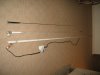
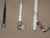
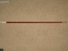
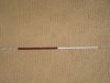
length of elements
feed location and method
relationship of one element to another
type of connector used

but of course the easiest way is to find a model number printed on the antenna and then just look it up.

good luck
 
Last edited:
Ron forgot to mention that a Vector Network Analyzer might cost shomewhere north of $100,000 USD. The poor man's Antenna Analyzer might set you back about $350.00 They are very different animals. I'm guessing the Gate Dip Meter is the modern semiconductor version of the old Grid Dip Meter that was implemented with a vacuum tube oscillator. Hamfests are great places to find esoteric test equipment.

Measure the length of the whip antenna in meters and multiply by four. Then use the formula
Code:
f requency(MHz) = 300 / wavelength(meters)
as a first approximation assuming that the whip antenna is designed to be a 1/4 wave vertical antenna.
 
Last edited:
...
Measure the length of the whip antenna in meters and multiply by four. Then use the formula
Code:
f requency(MHz) = 300 / wavelength(meters)
as a first approximation assuming that the whip antenna is designed to be a 1/4 wave vertical antenna.

This won't work if there is an obvious helical-wound wire under heatshrink on a fiberglas whip. Most CB and some 4-30Mhz Ham antennas are made that way. They are much shorter than a quarter wavelength.
 
Last edited:
This won't work if there is an obvious helical-wound wire under heatshrink on a fiberglas whip. Most CB and some 4-30Mhz Ham antennas are made that way. They are much shorter than a quarter wavelength.
True, but the OP did not mention those things. We can assume anything we want, but that doesn't mean it has any relevance whatsoever. He said wip[sic.] antennas with no mention of loading colis or helical wound wires -- sheesh

The only other thing he mentioned was bench testing and I think he got that answer.
 
Last edited:
Grid dip meters were not expensive. Lots if not most hams had them 40-50 years ago. Heath, Eico, Knight had kits. I built an Eico. I was maybe 16. I certainly did not have much money.
 
Maybe he's thinking of a Bird Wattmeter with a complete set of slugs. Its a different animal to be sure, but it has always been pretty expensive. Not VNA expensive, just ordinary expensive
 
Last edited:
True, but the OP did not mention those things. We can assume anything we want, but that doesn't mean it has any relevance whatsoever. He said wip[sic.] antennas with no mention of loading colis or helical wound wires -- sheesh

The only other thing he mentioned was bench testing and I think he got that answer.

Sheesh yourself! The OP is not the only person who reads these posts. Did you ever think that perhaps what I posted might be useful to the 50 or so other readers of this thread!
 
Last edited:
Sheesh yourself! The OP is not the only person who reads these posts. Did you ever think that perhaps what I posted might be useful to the 50 or so other readers of this thread!
Except what you posted was a qualitative description of things that might be. No mention was made of how to analyze them if they were there. I'll let the other 50 readers weigh in on the usefulness of your post.
 
I have photo's of the three aerial's The longest aerial is 2.360 ,
the middle one is 1.750 and the solid wire is 1.310 Meters long an I have photo's of the base area of the aerial's. I have placed a sketch of the long aerial to show what is at the base
I hope this helps.
 

Attachments

  • IMG_3083.JPG
    IMG_3083.JPG
    637.9 KB · Views: 218
  • IMG_3087.JPG
    IMG_3087.JPG
    689.7 KB · Views: 183
  • IMG_3088.JPG
    IMG_3088.JPG
    783.3 KB · Views: 174
  • IMG_3091.JPG
    IMG_3091.JPG
    774.3 KB · Views: 184
  • IMGVHF Aerial.jpg
    IMGVHF Aerial.jpg
    791.6 KB · Views: 189
Except what you posted was a qualitative description of things that might be. No mention was made of how to analyze them if they were there. I'll let the other 50 readers weigh in on the usefulness of your post.

Hey PapaBravo.
I'll just let the pictures speak for themselves. I'm not saying a word. :D

MikeML
 
They certainly do. They should have been included in the original post, which would have eliminated any doubt. The only way to draw any conclusions about their performance is to put them on an analyzer, unless RR can pull some magic out of one of his simulators.
 
Last edited:
I have photo's of the three aerial's The longest aerial is 2.360 ,
the middle one is 1.750 and the solid wire is 1.310 Meters long an I have photo's of the base area of the aerial's. I have placed a sketch of the long aerial to show what is at the base
I hope this helps.

In my opinion these are antennas designed for use on a vehicle and for frequencies somewhere in the range of 2 to 30 MHz. Amateur HF comes to mind, and perhaps CB 27Mhz. It is difficult to say exactly what frequency bands though. In general, the longer the antenna and the greater the number of turns of wire, the lower the frequency. That long one with the many many turns of wire seems to be for the lowest frequency (perhaps 14 or 7 MHz?). When we see the coil pitch change dramatically in a short distance, this might indicate a design for multiple bands.
 
Last edited:
OK, here goes with some inspired guess work!

All the antennas are for 27Mhz CB.
They were all made be "GME", (the black one certainly was).
The black one was intended to mount on a road vehicle.
The white ones were intended to mount on boats.

The white ones are loaded to present a high impedance feed point to minimise the loss due to being fitted to a fibreglass boat.
As a general rule a monopole antenna needs a conductive ground plane to work against, in a metal bodied vehicle this is easy, the bodywork is idea. A fibreglass boat? difficult unless the boatbuiler made special provision by incorporating a conductive mesh or whatever when he built it.

The longer white antenna has a built-in matching circuit to provide a 50ohm feed to the radio. This antenna looks fit for the scrap bin!

The shorter white antenna probably has the matching unit in the base and is useless without it.

To run a meaningfull test on any of these antennas would require the mounting/matching base, suitably mounted on something representative of the normal working location.
As for the test equipment to use, an antenna analyser would be favourite, a cheaper solution would be a 27Mhz CB radio and a VSWR meter.

JimB
 
Thank you for your explanation on this subject as the disciption is very informative.
Can you tell me what is a good VHF aerial for a fiberglass boat.
Or can I modify one of the antenna"s if so where can I get the information on how to modify the aerial as this would be good experience. Which aerial would I use.
Thank"s again for your help.
 
The aerial connects to a UNIDEN MC535 VHF Marine Radio
Transmit Frequency Range 156 to 158MHz
Reciver Frequency 156 to 16 MHz
1W / 25W
The aerial will connect to a fiberglass boat.
 
Status
Not open for further replies.

Latest threads

New Articles From Microcontroller Tips

Back
Top