Hi,
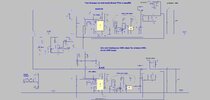
The attached (LTspice and jpeg) shows two Average current mode Boost PFC’s in parallel, and with all the “gubbins” that’s needed to facilitate this. (only 200W, because its purely a demo)
The secret is in the copying over of the Masters MOUT pin voltage over to the slave.
It also needs to use current sense transformers, and hence the duty cycle clamp cctry , which limits duty cycle to 0.9max, allowing the current sense transformers to always get reset.
Can you think of a lower component count way to do this?