Continue to Site

Welcome to our site!

Electro Tech is an online community (with over 170,000 members) who enjoy talking about and building electronic circuits, projects and gadgets. To participate you need to register. Registration is free. Click here to register now.

  • Welcome to our site! Electro Tech is an online community (with over 170,000 members) who enjoy talking about and building electronic circuits, projects and gadgets. To participate you need to register. Registration is free. Click here to register now.

Turning Transistors ON and OFF -- Grounding the Base?

Status
Not open for further replies.

Jessehk

New Member
Hi everyone.

I'm a 2nd year electrical engineering student who is making sure to get more involved in the practical side of things rather than just the extensive theory that we cover.

I bought the "All New Electronics Self-Teaching Guide" which has so far been extremely useful. I sometimes get annoyed when for example, the complex arithmetic involved in AC circuits is ignored and instead done in two parts with real numbers (once for the magnitude, once for the angle), but since I can mentally connect the theory and practice, it doesn't bother me. Anyways...

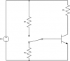
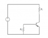
My question involved transistors. Specifically, the book discusses using transistors as high-speed switches controlled by a mechanical switch. When the switch is open and the BJT is OFF, the attached diagram is shown in the book. My question specifically is Why does base have to be grounded (rather then just disconnected) and assuming it is grounded, why is R_2 necessary at all?.

If the switch was open and line was not grounded, there still wouldn't be any base current and therefore the transistor would still be OFF. I don't understand.

Can anyone explain? :confused:
 

Attachments

  • trans-off.png
    trans-off.png
    5.2 KB · Views: 868
Last edited:
A transistor has capacitance between each pin. If you let a base float then its capacitance to the collector and emitter keep it turned on for a while when the base current is turned off. A resistor from the base to the emitter discharges this capacitance quickly so the transistor can turn off quickly.
 
A transistor has capacitance between each pin. If you let a base float then its capacitance to the collector and emitter keep it turned on for a while when the base current is turned off. A resistor from the base to the emitter discharges this capacitance quickly so the transistor can turn off quickly.

Thanks for the quick response. :) I'm going to ask some more (possibly very stupid) questions. Please excuse my ignorance.

If you let a base float then its capacitance to the collector and emitter keep it turned on for a while when the base current is turned off.

Why would capacitance keep the transistor on with no current? Does it have to do with a voltage between the base and the collector?

A resistor from the base to the emitter discharges this capacitance quickly so the transistor can turn off quickly.

Why not just make it a short? Why the resistor? Does it have to do with not overheating a wire with excess current?
 
Last edited:
Why would capacitance keep the transistor on with no current? Does it have to do with a voltage between the base and the collector?
Because the capacitance provides the base current to kerep the transistor turned on while the capacitance is discharged by the base current.

Why not just make it a short? Why the resistor? Does it have to do with not overheating a wire with excess current?
a short will discharge the capacitance extremely quicjkly but then the transistor will never turn on again until the short is removed.
With a resistor then the signal source can drive the resistor and turn on the transistor then the resistor turns off the transistor.
 
There is another, more insidious reason for providing a DC path to ground for a transistor that is supposed to be OFF. That is the reverse leakage through the collector to base junction, especially at elevated temperatures. Having a resistive path to ground prevents the current gain (β) of the transistor from amplifying the reverse C-B leakage. If there is no path from base to ground, then all of the leakage gets amplified by β.
 
Thanks to both of you for your responses.

then the transistor will never turn on again until the short is removed.
With a resistor then the signal source can drive the resistor and turn on the transistor then the resistor turns off the transistor.

Could I ask you to expand on this? It's still not really clear to me.

MikeMl: I think I understand what you are saying. So if there was no path to ground, there is REVERSE current flowing from the collector through the base (I am going to to take your word that this happens :p) that would turn the transistor on and the emitter current would be that reverse current amplified by β? Why would a path to ground be prevent this? I'm still confused.

Once again, I apologise for my ignorance. :)
 
Last edited:
Some circuits posted here and on other forums actually do omit the base-emitter resistor. These are generally not speed-critical, and are not meant to operate at high temperatures. Either that, or they are the result of sloppy design or ignorance.:D It makes me feel sorta like I do when I ride in a car without buckling my seat belt.:eek:
I have designed literally thousands of circuits in my career, and I don't think I have ever omitted the base-emitter resistor in a common emitter circuit.
 
Last edited:
...I think I understand what you are saying. So if there was no path to ground, there is REVERSE current flowing from the collector through the base (I am going to to take your word that this happens :p) that would turn the transistor on and the emitter current would be that reverse current amplified by β? Why would a path to ground be prevent this? I'm still confused...

Stare at the four cases below. I plotted the collector current for all four cases as a function of temperature. Note that case 1 is just the reverse CB leakage. Look at what happens to it depending on what is going on with the base (floating, grounded through a resistor or hard grounded)
 

Attachments

  • Thermal.png
    Thermal.png
    35.7 KB · Views: 476
Could I ask you to expand on this? It's still not really clear to me.

Imagine your circuit sitting on the table and your transistor base is shorted to ground. How are you going to turn it on?

1. Remove the short to ground
2. Apply current to base

Now imagine that the base is connected to ground through a ressitor. How are you going to turn it on?

1. Apply current to base.
 
Thanks to all of you for your responses (Noggin for the clear explanation and MikeMl for the great schematics and graphs).

I have a feeling that my initial drawing wasn't as clear as it could be. Theres a SPDT switch involved that I failed to draw initially.

I don't have use of my laptop until Monday, but when I get it back I'll be sure to post a more accurate drawing and ask a few more questions about everything you have all posted in order to make sure that I understand it.

Thanks again! :)
 
Sorry for my absence. School started up and I got very busy very fast.

I'm attaching a full circuit diagram. Do the above explanations still make sense in this new context? I'm afraid I'm still not very clear on all this... :(

I've also emailed the author himself (with a link to this thread), but I haven't heard back yet.

As always, help is appreciated. :)
 

Attachments

  • circuit-question.png
    circuit-question.png
    5.9 KB · Views: 459
Hello there,


As others have pointed out collectively, there are two main reasons for wanting to
ground the base of a transistor either directly or more usually through a resistor.

1. To turn the transistor off fast.
2. To keep the transistor from turning back on through it's collector to base leakage.

With 2 above, the resistor keeps the voltage at the base low so that it can not
get up to the required 0.6v or so that would start to turn the transistor back on
again.

With 1 above, the resistor 'sweeps' the charge out of the base region faster than
it would if it were left open or instead connected to a much larger resistance.

I must say though that even a resistor is not the ideal choice for turning off a
bipolar transistor as fast as possible. The best way is a resistor connected to
a minus (negative) power supply source like for example -5v or so. This causes
the charge to leave the base faster and thus turn it off faster than connecting
the resistor to ground. Once this action is deemed complete, the resistor can
again be connected to ground and this property gives rise to a turn off mechanism
sometimes known as "snap off", and is made with a little circuit to store just enough
energy to make this happen and not always require a negative supply.
The limiting factor when doing this is the reverse base emitter voltage rating, which
unfortunately for many transistors isnt very high at all so we can not connect it to
very low minus dc sources which would turn it off even faster.

There are also biasing techniques that can prevent the transistor from entering
saturation, which also speeds up the overall switching speed of the device.
 
Last edited:
I actually ran into this problem just a few days ago. We were using an opt-isolator between two PIC's to send serial data. The opto's datasheet showed the transistor's base left floating, so that is what we did in the design. Unfortunately, there was enough EMI from the switcher in the design that it caused the optop to go nuts and turn on... and it didn't happen until the production boards were potted. Very annoying.
 
Thanks for all your help everyone. The combination of all the explanations and also the response I received from the author have been extremely useful. I think I get it now.
 
Status
Not open for further replies.

Latest threads

New Articles From Microcontroller Tips

Back
Top