Continue to Site

Welcome to our site!

Electro Tech is an online community (with over 170,000 members) who enjoy talking about and building electronic circuits, projects and gadgets. To participate you need to register. Registration is free. Click here to register now.

  • Welcome to our site! Electro Tech is an online community (with over 170,000 members) who enjoy talking about and building electronic circuits, projects and gadgets. To participate you need to register. Registration is free. Click here to register now.

Turning on a TIP35C Transistor from a CD4017 IC

Status
Not open for further replies.
Your thoughts please!
Please draw transistor symbols correctly using the standard symbols.
Having to interpret your home made symbols is annoying.

JimB
 
Ok, have decided to go back to the idea of transistors. Attached is my completed circuit. Your thoughts please!

it is worth doing the experiment. Either it will work as you want or you will learn something as you troubleshoot,, test, redesign snd try again.
Best of all, there is very little risk if the design doesn't work (I.e. you're not going to hurt yourself or others and it won't burn your house down) so don't let other people convince you not to try it.

Good luck.
 
Please draw transistor symbols correctly using the standard symbols.
Having to interpret your home made symbols is annoying.

JimB

that's his perf-board layout. It's fine.
 
OK. But what he said was:

When it would have been more informative to say:


JimB
Yeah, but I'm in a forgiving mood because today is the great American Holiday - the day we celebrate by feeling sorry for a local kid who burns, mutilates or blinds himself or unintentionally (or intentionally) sets something ablaze.

im surprised you're not in a better mood, today's the day pubs reopen and you get to drink a pint through a mask.
 
There is so much voltage loss that there is not enough voltage to turn on three 3.6V blue LEDs.
The TIP35 will get VERY hot (it will need a pretty big heatsink) and the 2nd BC337 will get hot but will be fine:
 

Attachments

  • TIP35 LED driver.png
    TIP35 LED driver.png
    63.1 KB · Views: 183
Yeah, but I'm in a forgiving mood because today is the great American Holiday - the day we celebrate by feeling sorry for a local kid who burns, mutilates or blinds himself or unintentionally (or intentionally) sets something ablaze.
Spoken like a true cynic, a man after my own heart.

im surprised you're not in a better mood, today's the day pubs reopen and you get to drink a pint through a mask.
Indeed they do, in England.
However I am located in Scotland where the pubs are not yet scheduled to open.
But thank you for the suggestion, in the fridge I have a nice cool bottle of beer which will go down a treat in a few minutes.

Oh, before I forget, happy 4th July. You were well rid of us.

JimB
 
Spoken like a true cynic, a man after my own heart.


Indeed they do, in England.
However I am located in Scotland where the pubs are not yet scheduled to open.

Yep, pubs are open - but I don't have the slightest inclination to go and visit one :D

I did hear from a lady today though, she was stuck in traffic due to idiots queuing to try and get to the Tupton Tap in the middle of this map:


Considering the car park is full of tables for social distancing, not surprising they couldn't get in.
 
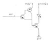
I'll say again, as I did in the previous similar thread, it's very poor to use a darlington in that way, as there's very little collector voltage on the BC337 collectors, and thus little current to drive the TIP35. It's FAR better to drive the BC337 collectors from the higher supply rails.

Even better, as there's three transistors, is to make the middle one PNP, fed from the collector of the first one, both of course powered directly from the supply rail - maximising base current for the TIP35.

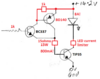
Or, as you say, use a suitable MOSFET.


Forgive my ignorance. Below I have drawn what I think you mean and have changed the resistor to the base of the first npn from 10k to 1.2k.
 

Attachments

  • img082.jpg
    img082.jpg
    41.9 KB · Views: 182
Using ordinary transistors providing a massive 8A of current when driven from a weak Cmos CD4017 you need the circuit to be like this:
EDIT; Driver transistor is a PNP BD140.
 

Attachments

  • LED 8A current circuit.png
    LED 8A current circuit.png
    51.9 KB · Views: 181
Last edited:
Thank you for your clarification and details for the circuit. I am an electrician in New Zealand so more used to 230vac or 3phase. My electronics kniwledge is quite limited but something I do find interesting.
 
Forgive my ignorance. Below I have drawn what I think you mean and have changed the resistor to the base of the first npn from 10k to 1.2k.

This was my thought, which allows full current drive adjustment in each transistor:

NPN_PNP_Driver.png


Resistor values can be tweaked accordingly.

Needless to say, R5 shouldn't be 1K :D
 
OK I have managed to find a supplier for the IRFP3206PBF mosfet. So lets start again. 10k between the 4017 and the mosfet?

no, you can use much smaller value resistor from CD4017 to gate. Like 1000 ohm for your slow switching speed. But use a 10k to 100k (any sizein between) from gate to ground).

note: the Mosfet gate is essentially a 1nF capacitor that you are charging, no continuous current flow like your other transistor..
 
Status
Not open for further replies.

Latest threads

New Articles From Microcontroller Tips

Back
Top