Continue to Site

Welcome to our site!

Electro Tech is an online community (with over 170,000 members) who enjoy talking about and building electronic circuits, projects and gadgets. To participate you need to register. Registration is free. Click here to register now.

  • Welcome to our site! Electro Tech is an online community (with over 170,000 members) who enjoy talking about and building electronic circuits, projects and gadgets. To participate you need to register. Registration is free. Click here to register now.

Turning a joystick pot control into voltage control inputs

Status
Not open for further replies.
Awesome, thanks for helping me get here. Is there anything special about the zener I should select besides 5.1V? I may have one available.

Yeah I did consider an overvoltage LED. I will work on that for final implementation.

I would definitely like to bias the input voltage divider to 2.5V instead of ground in order to shift the signal being clamped toward the center of the control axis (the virtual joystick if you will) rather than toward 0V. It works great in simulation. Under real life conditions I know I have to work out some considerations in choosing resistors for it: https://electronics.stackexchange.c...o-choose-value-of-resistor-in-voltage-divider

I also assume I need to place another resistor inline from the middle pot pin to give the 2.5V a consistent load. Should I just cut the input resistor value in half approximately and use the same value here?
 
the OP said:
Is there anything special about the zener I should select besides 5.1V?

Power is usually checked.

Before getting into the rest of what your trying to do, Impeadances matter. So, if the CPU has an input Z of 10 M. adding a few K of series resistance doesn't doo much. Your joystick pot effectively changes the POTS output Z with position.

So, voltage dividers work "properly" when they are connected to an ideal voltage source (Z=0). So, an example. Suppose the input Z of th CPU is 10 M. I could add two resistors 500K || 500K (+5/GND), middle to bias that input at 2.5V with nothing connected, but I have lowered the effective input Z of the system.

Another caveot is that OP amps and such are not ideal and there is always a little current flowing in the inputs. It could even be Femtoamps. If you don't provide a resistance for that current to drop across, the voltage builds up at the inputs. It's called a bias return path.

So, all of those ideal OP amp circuits don't work right unless you pay attention to the output Z of what's driving it.

Some time ago, I did a really neat over-range indicator for +-10V for a piece of laboratory instrumentation. I compared to +-110 and then triggered a bi-color LED for like 1 second.
 
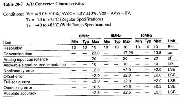
Yeah I understand the joystick was always changing its output impedances in real-time. I don't have a way of measuring that output or the CPU input impedance but the signal does have a 1k resistor (and 0.01uf to ground) before it reaches CPU pins. The input themselves have a capacitance of 15 pF. And I did find this:

05860a3c87b15a5558e55d63270250a7.png

And I'm sure the diode circuit has its own effect. I am only used to impedance as an audio consideration where things are okay if the output impedance is roughly at least 10x the next input stage impedance and regularly accept some gains and losses through passive attenuation and mixing etc. So it's confusing for me to see an "Allowable signal-source impedance" with a maximum but no minimum. The clocks are 20MHz and 12.5MHz but it looks like that doesn't change the impedance.

I had hoped to avoid an active solution but I guess an active DC buffer circuit to sum the inputs with 2.5V in the voltage divider and provide a relatively steady output impedance might be the right way, like this https://www.facstaff.bucknell.edu/mastascu/elessonshtml/OpAmps/OpAmp3Note1Buffer.html
 
the OP said:
So it's confusing for me to see an "Allowable signal-source impedance" with a maximum but no minimum.

0 for a minimum would work, but 0 is unobtainable except in simulation.

There actually is a way to measure input Z. Put POT in series with a source, any source. measure voltage at input. Adjust pot for 1/2 the measured voltage. Remove and measure pot R. That is your input Z.

Yup, buffers.
 
Sorry I had a few things come up and I've been processing all of this along the way.

Thanks so much for your help. I'm going to finish up a couple of easier projects, order parts, and then get going. I feel good about the basic design you mapped out for me. I already have several op amps on hand so I'll wait until I have the impedance measurement and test with some trusted <5V signals to determine the dual buffer design. In the meantime I can also think about how to mount the little board, where to poke holes in the case, etc.

And the impedance trick - it's weird I feel like I learned that a long time ago and somehow forgot even though it will be incredibly useful to me for a lot of other things. So thanks again.
 
Status
Not open for further replies.

Latest threads

New Articles From Microcontroller Tips

Back
Top