Thank you every one for your help, it is greatly appreciated and I'll certainly be taking it on board.
In answer to some questions:
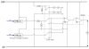
1) The top part of the switch is to switch between two sets of LEDs. Each LED will be labelled and it will tell the user whuch of the pressure sensors has been selected for measuring inlet pressure and which one for outlet pressure. As it actually switches the contacts into the comparator at the same time it removes any confusion that could occur if there were two switches
2) I've used the second comparator because i thought, misguidedly probably, that the output voltage of the comparator would be negative and by passing it through the inverting input I would get a poisitive voltage output.
3) I used the 74k resistors because there were a load in the workshop and as I wasn't worried about current I used them so they would stay cool in the plastic enclosue this thing will eventually go in.
C