Continue to Site

Welcome to our site!

Electro Tech is an online community (with over 170,000 members) who enjoy talking about and building electronic circuits, projects and gadgets. To participate you need to register. Registration is free. Click here to register now.

  • Welcome to our site! Electro Tech is an online community (with over 170,000 members) who enjoy talking about and building electronic circuits, projects and gadgets. To participate you need to register. Registration is free. Click here to register now.

TTL Clock with 7447 7490 and 7400 IC's

Status
Not open for further replies.
Pete61 said:
Guess Not!

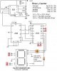
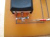
A can oscillator has four pins.

Thank you all anyway. I will continue experimenting.

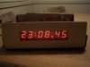
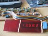
The clock is an anniversary present for wife. I have until Aug 1st to complete it.

I'm sure I will will have it all figured out by then.

Thank you all again and take care.

Did she say you have to use 74 series TTL?
 
I checked up on the 74160 which is a complete different IC than the 7490 IC's which are cascaded after each other, and are not synchronously driven.

The 74160 needs a bounceless positive edge clockpulse to advance the counting.

You may need to add a buffer or amplifier stage to drive the 74160 counters.

Get some 7490 IC's, they are cheap and will work.

Regards, Raymond
 
**broken link removed**


Here is a website that show how to connect the 7490 in all of it's divider configs.
 
Can anyone send me the simplest circuit of digital clock by using IC 74LS90-93, 74LS47 and 7 segment display to my email address "fhnaseer@yahoo.com", send it within one hour, I have to submit it to my teacher, it is a project for my semester, hurry up, within one hour,
 
Can anyone send me the simplest circuit of digital clock by using IC 74LS90-93, 74LS47 and 7 segment display to my email address "fhnaseer@yahoo.com", send it within one hour, I have to submit it to my teacher, it is a project for my semester, hurry up, within one hour,


Lol you fail.

heres a website to symbolize your failure :p

Fail Dogs
 
Maybe if he didn't spend the semester pulling his wire, he would have had time to draw this simple circuit. ;)
 
Can anyone send me the simplest circuit of digital clock hurry up, within one hour,

Here it is!

Oh, darn. Too late.

Anyway, just make up six sets of the attachment, but only one timer, of course.

I'll leave it up to you to figure out how to make it count to 12:59:59.
 

Attachments

  • Basic Counter.JPG
    Basic Counter.JPG
    39.4 KB · Views: 4,016
nice schematic iyung w, looks interesting.
I just have some questions with your ckt.
1. What is the voltage input of this ckt?
2. Your 74LS47, 74LS08, 74LS32 and other ICs are not connected to Vdd. Do I have to connect it to Vdd and GND for it to work?
3. Does the 1MHz oscillator needs Vdd also for it to function?

Anyone can answer pls. Thanks
http://www.geocities.com/iyung_w/files/24hrs_clock.pdf
 
For an accurate 60Hz timebase, you can use a 3.579545 MHz crystal with an MM5369, 8-pin IC with discrete components. Eliminate the ten-hour 7490 and 7447 with a 7474 D flip-flop and transistor wired as divide-by-two that is on from 10:00:00 to 12:59:59.
Out of curiosity, how would you set the time on this clock?
 
The MM5369 has not been made for many years. It needed a supply of at least 9V for its oscillator to work at the 3.58MHz crystal's frequency and its output current was much too low to drive old fashioned TTL. It was good in an accurate low power Cmos clock.
 
digital clock

Hello everyone am new to here but am looking forward for a good project that am planning. I would like to build a digital clock. I saw a lot of schematics some of the schematics dont really explain it very well for me since am a newbie in this and still learning. I would really apriciate it if someone showed me step by step on how to do it am currently building something in multisim but am stuck. thats why i would like to start over with someone who could explain step by step thank you very much.
 
Last edited:
Every year, students ask for the circuit for a digital clock that uses old TTL ICs.

Learn about digital logic then design the circuit yourself. Your teacher expects you to do that, not just copy the circuit from somebody else.
 
Here's mine. Works like a charm. 7490's with 7447's for the LEDs.

The daughter board is the bridge rectifier. I'm currently working on a new one. Same as the old, but has a better time setting circuit, and will be much smaller. The one that I build basically just uses switches to redirect the 1Hz time base into either the seconds, minutes, or hours sections.

The new clock is going to use a crystal so I don't have to bother with the 60 Hz line. I found a neat trick to get an easy, accurate 1 Hz time base for $6....

http://www.josepino.com/circuits/index?one_second_timebase.jpc
 

Attachments

  • clock1.jpg
    clock1.jpg
    38.7 KB · Views: 1,066
  • front1.jpg
    front1.jpg
    23 KB · Views: 866
Last edited:
Great ! Job well done krye.

I have been to busy with work to post a schema, and build an other TTL clock for which I have the parts and blue LED 7 segment displays.

Regards, Raymond
 
OK, before anyone blasts me with the "do your own work speech" let me let you that I'm 33, not in school, and this is a hobby. I already made a working 24 hour clock. (see attached pictures) It came out great. I even etched my own board.

I want to have a go at making a 12 hour version. Rev 2 of my clock will pretty much use the same board and chips (7490's and 7447s) I can get the clock to run in 12 hour mode, but the whole AM/PM LED is bothering me. I was going to add a flip-flop, but I can't for the life of me figure out how to get the LED to stay on when the hours read "12" and then off again 12 hours later.

Anyone have a schematic? I don't want to redo the clock using 7492s since I already have all the 7490s on hand.
 

Attachments

  • web1.jpg
    web1.jpg
    65.1 KB · Views: 1,247
  • web2.jpg
    web2.jpg
    115.4 KB · Views: 1,070
Here we clock again !

Hi Krye,

I don't think I ever built a clock, that makes me the ideal
person to give you some advice on how to build one.

Connect all R9's to gnd, that will make the clock count
instead of displaying six nine's.

QD of U5 and CLKA of U6 are both connected to +5 volt, that's
probably a typo.

The setting for minutes and hours is completely wrong.

And . . . the hours counter will count from 0 to 13 ?????

As I said before, I don't know much about clocks so I could
be wrong. :D

on1aag.
 

Attachments

  • Diode AND gate.GIF
    Diode AND gate.GIF
    5.3 KB · Views: 1,011
Hi,

I built a clock 14 years ago using 4000 series chips. I built it on breadboard and used it as my bedside clock for many years. Never got around to putting it in a proper case (as with a lot of the projects I used to build). It was probably one of the last things I built before abandoning hobby electronics until my resumption very recently.
 

Attachments

  • Clock 001.jpg
    Clock 001.jpg
    316.6 KB · Views: 1,156
  • Clock 002.jpg
    Clock 002.jpg
    296 KB · Views: 942
  • Clock 003.jpg
    Clock 003.jpg
    467.7 KB · Views: 1,259
  • Clock 004.jpg
    Clock 004.jpg
    430.3 KB · Views: 918
  • Clock 005.jpg
    Clock 005.jpg
    387.5 KB · Views: 1,070
  • clock 008.jpg
    clock 008.jpg
    49 KB · Views: 1,077
  • clock 009.jpg
    clock 009.jpg
    34.4 KB · Views: 1,066
Status
Not open for further replies.

Latest threads

Back
Top