Continue to Site

Welcome to our site!

Electro Tech is an online community (with over 170,000 members) who enjoy talking about and building electronic circuits, projects and gadgets. To participate you need to register. Registration is free. Click here to register now.

  • Welcome to our site! Electro Tech is an online community (with over 170,000 members) who enjoy talking about and building electronic circuits, projects and gadgets. To participate you need to register. Registration is free. Click here to register now.

Trying to repair electrical heating pad (TK-HP2412)

Status
Not open for further replies.

bojanv55

New Member
I bought this heating pad, and it worked 5-6 times I tried it (for 2-3 days). Then one day it just didn't want to heat. I somehow managed to make it heat 1 more time after this (I do not know how - pure luck), and since then no matter what I try it will not heat (I just try to change settings, plug-unplug cables). In instruction manual it is written that it is broken if all LED lights are flashing, but when I connect it to power all LEDs are ON (as it should work normally) - but it is not getting warm at all.

This is the video where I just turn it ON - but no heating: Youtube Video (If I connect controller without blanket attached, all LEDs are blinking - it recognizes that blanket is not connected). The only thing that warms-up is upper part of controller (I guess there is this yellow transformer).

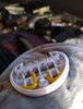
I managed to measure resistance on 4 blanket pins, and only pins 1-4 seem to give some output (225 OHMS), and other pins seems like not connected at all.
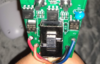
When measuring voltage on controller output pins (also 4 pins) I get some readings (It is written on the picture attached here with controller - I measured voltage when blanked was not connected and LEDs were blinking since controller knew it has no blanket connected).

The fuse seems to be ok, since controller LEDs are ON when I turn it ON - so I guess it is not that. All capacitors seems to be ok visually.

Any recommendation what could I do?
 

Attachments

  • controllerback.jpg
    controllerback.jpg
    221.6 KB · Views: 471
  • controllerfront.jpg
    controllerfront.jpg
    947.2 KB · Views: 525
  • controller.jpg
    controller.jpg
    725.4 KB · Views: 455
  • heatingpad.jpg
    heatingpad.jpg
    1.4 MB · Views: 457
Last edited:
A couple of things. if there is a triac, voltages will be out to lunch unless there is a load.

There should be a ribbed side of the cable and this should be neutral.

Look at the heating element first, resistances from the ribbed side of the cord.

It might be helpful to know how it's supposed to work, e.g. three heat settings. Continuous. Timer.

if we assume 3 settings, ty should have two elements. Just like a 3-way bulb it will give you three settings.

Yuu have blu, blk, orange and yellow. probably it work with A, B and AB to give you three heats. What's the designation to to the blanket other than H and L.. That will be a clue.

What's the wattage of the blanket. have an 7 and 15 W night lights (incadesent)?

best guess:
On/Off
each led illuminated for a higher power.

you seem to have 5 wires going to the blanket.. Guess 2 heating elements and one thermister element.
First key: labels on the wires and resistances based on the labels.
 
There are 4 wires going to the blanket. On those images I posted, I wrote voltage measurements between each of the pins.

Blanket is 75Watts.

On controller there are 6 Heat levels, and 4 timer settings (30, 60, 90, 120 minutes).

Blue (connection labeled as N) and Brown (connection labeled as L) wires are the one coming from power outlet to the controller. Other wires are going to the blanket (4 of those - white (labeled as R), yellow (labeled as R), red (labeled as H) and black (labeled as H)).

BTW. there is a video where you can check how controller works and how cable looks like (I think there is no ribbed side on this cable).

And here is a better image of elements in the lower part of the controller (I guess those are triac's - BT136S-800):
 

Attachments

  • Screen Shot 2020-10-13 at 10.20.19 AM.png
    Screen Shot 2020-10-13 at 10.20.19 AM.png
    740.6 KB · Views: 338
Last edited:
OK, I guess this is the reason - seems like one of the wires got burned (that can be seen in the image). I still have to re-solder the wire and try again, but not sure if same problem will reoccur. Not sure why this happened in the first place.
 

Attachments

  • IMG_20201014_151049490.jpg
    IMG_20201014_151049490.jpg
    72.5 KB · Views: 450
I can;t tell 100% of what's going on, but what I think:

1. Wire is not tinned copper
2. Flux was not removed
3. Wires were not soldered properly
4. Not all strands connected created a local hot spot.
5. The pins are tubes, not pins
6. A dissimilar metal problem. (Battery formed and corrosion started)

Looks like it's going to be a difficult fix. I'd use 60/40 solder with a water soluable flux Clean off the flux well after soldering. Cover exposed metalics with liquid tape.
 
Status
Not open for further replies.

Latest threads

Back
Top