billymac4511
New Member
Hi there! I'm looking for assistance in identifying a part I have. Let me offer a little background first.
I have a 3kw/6300w-peak inverter in my Jeep.
Due to vibration (Jeep is off-roaded most weekends) two of the cement resistors have fallen off the board.
The resistors in question actually total 4 that were wired onto the board, but were stacked 2-high in two separate spots. The wires pulled out of the end of the cement on the top resistor on each 'stack'.
I THINK they are 15W 1ohm resistors, but other than that, I've got no idea. This is from info I've googled. Trust me, I've googled off and on for about three weeks now and I can't seem to find a 100% sure answer, so I thought I'd ask some folks that obviously know what they're doing! LOL")
Radio shack sells 10W 1 ohm and 15W 10ohm, but neither are the same as what I think I've got. I really don't know the voltage that they are...
The 'top' resistor's (the ones that fell off) wires were simply twisted around the bottom resistors (still on the board with the wires wrapped around them and securely soldered to the printed board). So, because of this, I'm fairly confident that if I can find the exact replacement parts, I can just untwist the old wires and remove them, and re-twist CAREFULLY the new parts on to the board. Then I hope to brace them some how so this doesn't happen again... I haven't figured that part out yet. I still need to find the replacement parts!
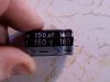
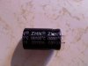
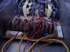
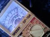
Anyway, here are some pictures of the application and of the specific resistors I've got with the wires broken off just inside the ceramic.
**broken link removed**
**broken link removed**
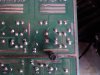
in the first pic you can see the specific part. In the second, you can see the two locations where they came from, the wires that came out of the cement, still sticking up from the two that are still attached to the board.
Any help with identifying these two resistors (they're the same, so... if you can identify one of them LOL...) I'd really appreciate it... if you can point me in the direction of where I can buy them (radio shack doesn't look good...) I'd GREATLY appreciate it!
Lastly, would it be possible to replace the 'double' resistor setup at each spot to a single resistor that did essentially the same thing, lessening the chance that they are going to vibrate off again?
I'm decent with a soldering iron, but definitely not a master... I think I could pull off this solder job, it's actually pretty sizable on the printed side of the board so there's lots of room for errors by a novice (like me!)
I have a 3kw/6300w-peak inverter in my Jeep.
Due to vibration (Jeep is off-roaded most weekends) two of the cement resistors have fallen off the board.
The resistors in question actually total 4 that were wired onto the board, but were stacked 2-high in two separate spots. The wires pulled out of the end of the cement on the top resistor on each 'stack'.
I THINK they are 15W 1ohm resistors, but other than that, I've got no idea. This is from info I've googled. Trust me, I've googled off and on for about three weeks now and I can't seem to find a 100% sure answer, so I thought I'd ask some folks that obviously know what they're doing! LOL
Radio shack sells 10W 1 ohm and 15W 10ohm, but neither are the same as what I think I've got. I really don't know the voltage that they are...
The 'top' resistor's (the ones that fell off) wires were simply twisted around the bottom resistors (still on the board with the wires wrapped around them and securely soldered to the printed board). So, because of this, I'm fairly confident that if I can find the exact replacement parts, I can just untwist the old wires and remove them, and re-twist CAREFULLY the new parts on to the board. Then I hope to brace them some how so this doesn't happen again... I haven't figured that part out yet. I still need to find the replacement parts!
Anyway, here are some pictures of the application and of the specific resistors I've got with the wires broken off just inside the ceramic.
**broken link removed**
**broken link removed**
in the first pic you can see the specific part. In the second, you can see the two locations where they came from, the wires that came out of the cement, still sticking up from the two that are still attached to the board.
Any help with identifying these two resistors (they're the same, so... if you can identify one of them LOL...) I'd really appreciate it... if you can point me in the direction of where I can buy them (radio shack doesn't look good...) I'd GREATLY appreciate it!
Lastly, would it be possible to replace the 'double' resistor setup at each spot to a single resistor that did essentially the same thing, lessening the chance that they are going to vibrate off again?
I'm decent with a soldering iron, but definitely not a master... I think I could pull off this solder job, it's actually pretty sizable on the printed side of the board so there's lots of room for errors by a novice (like me!)
Attachments
Last edited:
")