Continue to Site

Welcome to our site!

Electro Tech is an online community (with over 170,000 members) who enjoy talking about and building electronic circuits, projects and gadgets. To participate you need to register. Registration is free. Click here to register now.

  • Welcome to our site! Electro Tech is an online community (with over 170,000 members) who enjoy talking about and building electronic circuits, projects and gadgets. To participate you need to register. Registration is free. Click here to register now.

Trouble with wiring Motion Sensors

Status
Not open for further replies.
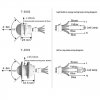
I'm attempting to set up and wire 8 PiR motion sensors, however by the wiring diagram, some of the terms used for some of the wires kind of confuse me a lot.
One brown wire reads off as fire wire and another blue one reads off as null (or zero) wire while the other two, being yellow and secondary blue, connect apparently to a drive(driver) or ballast before connecting to a light, specifically an LED. I have an educated theory of how I would wire them but now I'm just trying to better understand the proper meaning and follow a more step by step wiring diagram so I could make my own from there, could anyone tell me what these names used for these wires mean and how I can go about wiring these sensors but for usages requiring portability. And I haven't even found a proper solution for a power source yet. Please help.
 

Attachments

  • 25mm-40mm-PIR-Human-Sensor-Motion-110V-220V-IR-Detector-Infrared-Switch-Time-Delay-Adjustable-...jpg
    25mm-40mm-PIR-Human-Sensor-Motion-110V-220V-IR-Detector-Infrared-Switch-Time-Delay-Adjustable-...jpg
    32.9 KB · Views: 451
That looks like UK standard colours. Brown is live, blue is neutral.

Mike.
 
So could Brown also be power/data? (Looked up firewire and apparently it's definition is the following: "a technology that allows high-speed communication and data exchange between a computer and a peripheral or between two computers." Which confused me more but also makes me happy cause if read correctly I can also add some sort of brain (or processor) and run intricate commands, if I can figure out if that's even correct.
 
Firewire is an old fast serial system that is pretty much redundant now. I suspect a translation error, What in the UK is called live is called hot in th US so I suspect hot wire has been translated into fire wire. My guess is that it's simply a switch.

Mike.
 
Yes, it's simply a switch - the two blue wires (neutral in and neutral out) are simply joined together inside (purely for wiring convenience), the brown is live in, and the yellow is switched live out.

As Pommie has already mentioned, it's got nothing whatsoever to do with Firewire, it's just a simple mains switch.
 
My educated guess for wiring and completing the circuit I had in mind was to use the yellow and first blue and connect them to vibration motors and the brown and secondary to an arduino or raspberry pi as the data to program but also power. Think this would work at all?
 
That unit appears to be designed to run directly from 220-240V AC (in on the brown & blue wires) and the output is the same voltage as the supply, when they are triggered.

eg, There is an internal contact or solid state switch that connects brown to yellow to feed power on to a 220/240V lamp.

They are not in any way suitable for low voltage circuits.

To work with low voltages and have separate output switch contacts, look at burglar alarm PIR sensors - they generally work from a 12V supply and have a switching circuit you could use to control a logic-level input.

Examples: https://www.ebay.co.uk/sch/i.html?_nkw=alarm+pir+wired&_sop=2

This is the instruction manual for a typical alarm sensor PIR unit - you can see the screw terminals for the 12V power supply in to it, and the "alarm" contact terminals that switch when it senses anything.

The "tamper" terminals are linked to a switch in the casing, that breaks the circuit if the cover is removed. You don't need to use those.
 
Yeah, I figured out about 5 days in after weeks (approximately almost 3 roughly) that these sensors I've bought are more of an industrial type application and high - higher voltages will be needed to power not only one but multiple alone. My further research has lead me to buy up a few pieces of Micro circuits (Buck converters and rectifiers) to lower the voltage all to 12v and 5 - 3.3v's so that way I'd be able to regulate the power safely and hopefully use these sensors (ironically enough I am using ring terminals of all forms and applying them to my design and the circuit diagrams to allow me to power all of the "firewires" and "Null (or Zero) lines" through the circuit boards I'm designing. Hopefully should all things go well I can reduce the power significantly and run a controlled system. So how would I go about wiring these to vibration motors as the trigger switches rather than LED's or lights (or ballasts and such)
 
You just cannot use the ones in your original post with low voltage circuits - they need roughly 230V AC in so they can function and they give the same out when triggered.
They are suitable for movement-sensing control of house, office or factory lighting and that is all.

The supply voltage is lethally dangerous and not suitable for experimentation.


You need a totally different type for low voltage circuits such as the 12V - 5V - 3.3V you mention, such as the alarm sensors I linked to earlier.
 
Status
Not open for further replies.

Latest threads

New Articles From Microcontroller Tips

Back
Top