Continue to Site

Welcome to our site!

Electro Tech is an online community (with over 170,000 members) who enjoy talking about and building electronic circuits, projects and gadgets. To participate you need to register. Registration is free. Click here to register now.

  • Welcome to our site! Electro Tech is an online community (with over 170,000 members) who enjoy talking about and building electronic circuits, projects and gadgets. To participate you need to register. Registration is free. Click here to register now.

Trouble with multiple voltage dividers

Status
Not open for further replies.

AndyFe

New Member
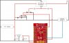
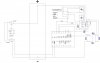
I’m using an ESP8266-DEV to measure battery voltage and control some LED lights.

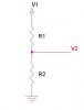
The first 2 voltage dividers are used to get the voltage bellow 1V, required by the ADC GPIO – it is working fine.

The third voltage divider lower the voltage bellow 0.4V, in order to power down the Pololu S10V2F12 12V step-up, by keeping the SHDN pin powered during sleep cycles of the ESP.
By setting GPIO12 on HIGH, the 12V module activates, and through IRL510 MOSFET I can control the LED light.

In my prototype the circuit works fine, but on my PCB design the third divider either not give me any voltage, or give me the same voltage as input, and the MOSFET is behaving glitchy – every couple of seconds it turn off and on. I’ve even managed to burn one ESP...

I’ve measure all wirings and connections, I do not have any shorts or wrong voltages... What am I missing? What else can I measure to identify the source of the problem?
 

Attachments

  • Wiring.jpg
    Wiring.jpg
    106.6 KB · Views: 188
  • PCB Wiring.jpg
    PCB Wiring.jpg
    80.8 KB · Views: 170
You probably have the connection on the ESP configured as an output. If so, it will be high or low, giving you the voltages that you have seen. The MOSFET behaving erratically is probably due to the gate connection on the ESP being configured as an input, so the MOSFET gate is floating.
 
Diver300 is right for the main issue. The regulator is always on because the diodes are in the wrong way, the regulator module can be switched off only by pulling low the SHDN pin. Why such a complicated divider, only three resistors are enough. Tough , I don't think that switching off on low voltage with the left diode will work reliably , SDHN is a logic input , not a comparator input. You don't need to turn off the mosfet if you turn off the regulator.
Edit
However , the accuracy for li batteries voltage must be pretty high so it's wise to use a separate divider for ADC.
 
Last edited:
Diver300 - the GPIO15 is configured as output, this is how I enable the regulator, setting it to HIGH send 3.3V to SHDN pin... the gate connection pin is configured as PWM, so I guess output... do I need to configure it as output too?

mdorian - as I understood from documentation, in order to switch off the regulator I have to connect <0.4V to SHDN pin, wich is done through the 3 voltage dividers. Having a variable voltage, even if its less than 0.4V, would not work reliable with the regulator shutdown feature? I should provide stable current?
And what do you mean by diodes in the wrong way - the current must flow from the voltage divider to the SHDN, and from GPIO15 to SHDN - I'm missing something?
And with the complicated dividers, you are right, thank you :) I had only 1K and 2K to play with. I will switch the design to separate dividers for ADC and SHDN...and what do you mean by turning off the mosfet?
 
1) SHDN pin has an internal pull-up resistor so you need to pull it down. The way the diodes are connected is impossible to do that. In this configuration the regulator is always on.
2) In the documentation states that the regulator is off for SHDN less than 0.4V but there is no information for the ON voltage , it might be on even 1V or more, there is always a voltage "no man's land" where the regulator state is uncertain or unstable. You should see what integrated circuit is used and look it's datasheet. Take a closer picture where I can see the markup in it or read-it and post-it.
3) You can make higher divider ratios with simpler schematic: V2/V1 = R2/(R1+R2) where you can use many resistors in series and the total value will be sum of resistor values.
Again , shutting down the regulator/ converter like this will never work , you either use a much complicated schematic with a voltage comparator or gave up and use only software shoot off with the right side diode ( backward as I pointed out before) .
 

Attachments

  • New Bitmap Image (4).JPG
    New Bitmap Image (4).JPG
    6.6 KB · Views: 195
mdorian - Now I've seen my mistake with diodes, thank you. I've tried applying 3.3V to the SHDN pin and it activates the regulator. And yes, I've changed my overly complex voltage dividers with 2 separate ones, with proper resistance values :)

Many thanx! Back to testing...
 
Status
Not open for further replies.

Latest threads

New Articles From Microcontroller Tips

Back
Top