Continue to Site

Welcome to our site!

Electro Tech is an online community (with over 170,000 members) who enjoy talking about and building electronic circuits, projects and gadgets. To participate you need to register. Registration is free. Click here to register now.

  • Welcome to our site! Electro Tech is an online community (with over 170,000 members) who enjoy talking about and building electronic circuits, projects and gadgets. To participate you need to register. Registration is free. Click here to register now.

Triac Inductive Woes, ACS108 Snubberless, Z010X

Status
Not open for further replies.

ACharnley

Member
Hi,

Here I've a problem that's driving me bonkers.

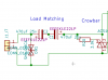
I have an inductive AC supply, about 3 ohm and I'm attempting to clamp the voltage with a triac.

First the standard Z010X series (I have tried all 3-25mA sensitivities).

Using a back-to-back zener arrangement the triacs work correctly over 33V, however I have spikes which a TVS can't absorb as the breakdown curve is too close to the absolute maximum rating of my other components (40V). So, I take the zeners down to 27V to give the (also lowered) TVS some headroom and now the triacs don't turn off. A data logger shows I have oscillation - the voltage remains at 27V at point of turn on/off.

Introducing snubbers, no variation of R and C is able to deal with it. 0.01F and around 20 ohm sees some action but the capacitor burns up. Even so it doesn't turn off until the AC frequency is far lower, not just under the zeners threshold.

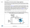
Introducing the ACS108 (which on paper looks like a golden solution). I installed it but so far it doesn't work as expected, or as stated in the datasheet.
  • If I short gate and com, which should result in engagement, there is no clamp.
  • If I apply 15v zeners between gate and com there is no clamp at any voltage.
  • If I apply 30V zeners between gate and com there is a clamp at 33V but the voltage continues to rise a bit (enough to breach the 40V). So it is partially effective.
The datasheet has a usage example as an over-voltage trigger using a 220ohm resistor. Yet in the spec it says the maximum positive gate voltage is 10V. It's getting plenty more than that on AC mains! You can see from my schematic I was intending to follow this example with a lower resistance to switch on around the 30V mark but haven't been able to make it work yet.

Your help or suggestions very appreciated!
 

Attachments

  • Screenshot_2018-08-11_18-25-11.png
    Screenshot_2018-08-11_18-25-11.png
    8.4 KB · Views: 145
  • Screenshot_2018-08-11_18-23-50.png
    Screenshot_2018-08-11_18-23-50.png
    123.4 KB · Views: 140
  • Screenshot_2018-08-11_18-23-16.png
    Screenshot_2018-08-11_18-23-16.png
    63.1 KB · Views: 193
The datasheet has a usage example as an over-voltage trigger using a 220ohm resistor

You are misunderstanding the data.

The transient test with the 220R resistor is a near-destructive high voltage overload withstand example - a 2000V spike which can be repeated "up to ten time" for each polarity in the lifetime of the device.
It's a demonstration of the level of overload they can stand without failure.


In normal use it works as a sensitive gate triac, needing no more than 10mA gate current so it's possible to drive the gate from a logic circuit with just a resistor rather than needing the usual high-current (150mA or more) gate drive.


Also remember that thyristors and triacs do not turn off until the current through the main terminals drops to zero. Once triggered, the rest of the half cycle will be shorted out on an AC supply.
 
OK that part I suspected as much.

So according to the datasheet, if I were to sink the gate on this triac to ground (post rectification), it would turn on?

Only, it doesn't. :)
 
No, it need a 10mA current in to the gate (relative to common) to switch it on. Connecting to common should lock it off.
 
Connecting it the gate to gnd, I can see oscillation in effect (voltage almost doubles) while there's no clamping.

Probably time to give up with triacs!
 
How did you come to that conclusion?

Despite the rather confusing text, fig. 19 in the datasheet (based on the fig. 18 circuit), clearly shows a moderately high voltage. 370V or so, across the device before it is triggered by the 2KV spike.

If it were triggered by input to com connection it would be permanently on.

Also, the "direct to logic" input could not work over any range of voltage if the input itself had a voltage on it, that needed pulling down; it could damage the ICs connected to it, as many cannot stand an external voltage above their own supply volts being applied.
 
For a clamp, I'd try a normal bipolar transistor with a zener in series with a low value resistor between base and collector, plus another resistor base-emitter to prevent any turn-on due to leakage. Add a high-speed rec in series for reverse polarity protection.

Two of those connected opposite ways should work on AC.
 
Status
Not open for further replies.

New Articles From Microcontroller Tips

Back
Top