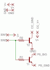
Hello all,
I've come up with a circuit that'll (hopefully) switch on both a button on a PlayStation controller and a corresponding cold cathode light using transistors. The PlayStation controller is a 3.4v signal while the voltage to the cold cathode is 12v from a separate power supply (wall wart). My questions are, will this circuit work? Must I connect the emitters of both transistors together to a single ground? Will the different voltages affect/do harm to anything? Will sharing/connecting the two grounds affect/do harm to anything? Do I need isolation between the separate 12v/ground and PlayStation signal (3.4v)/ground? Thanks.
LEGEND:
V+: 12v (from external power supply)
GND: ground (from external power supply)
CC_GND: cold cathode ground
CC_V+: cold cathode V+
SW1/SW2: switch pads
PS_SIG: PlayStation signal
PS_GND: PlayStation ground
R1/R2: current limiting resistors
T1: 2N4401
T2: TIP31C
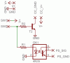