Continue to Site

Welcome to our site!

Electro Tech is an online community (with over 170,000 members) who enjoy talking about and building electronic circuits, projects and gadgets. To participate you need to register. Registration is free. Click here to register now.

  • Welcome to our site! Electro Tech is an online community (with over 170,000 members) who enjoy talking about and building electronic circuits, projects and gadgets. To participate you need to register. Registration is free. Click here to register now.

Transistor...power 18LED's?

Status
Not open for further replies.
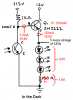
I have a project where I want to switch on 18 LED's on and off together, schematic I followed is here:

https://www.evilmadscientist.com/article.php/nightlight

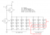
Now instead of switching on 1 LED, I will be switching 18. Of the 18 LED's 12 are 5mm white (Vf = 3.0V, If = 25mA, 3500mcd) and 6 3mm blue (Vf = 3.5V, If = 30ma, 1000mcd). The powersupply is 12v.

Now I used on online calculator which suggested for the white LED's supplied with 12v to have 4 in series (with 1ohm resistor) and then in parallel 3 times. The blue will be 3 in series (with 56ohm resistor) and then in parallel 2 times.

Now the total current for the white LED's is 75ma with 902mW of power, while the blue LED's is 60ma with 731mw of power. Now all I really have for "common" transistors is the 2N2222...is there any way I can parallel or split the load to allow these transistors to carry this load? How?

Or what would be a good alternative single transistor solution? I'd be more inclined to make what I have work (using the 2N2222) since I have to get this done by the 24th of this month. :D
 
Four 3.0V white LEDs in series rotal 12.0V. So if a 12V supply is used then there isn't any voltage across the 1 ohm current-limiting resistor so there is no current. The online calculator made a big error.
Also, the driving transistor needs about 0.8V across it.

The "3.0V" LEDs are 2.8V to 3.2V. Some of them might be exactly 3.0V.
So connect three 3.0V white LEDs in series and use a 100 ohms resistor in series to limit the current to 22mA. If the LEDs are actually 2.8V then the current will be 28mA. If the LEDs are actually 3.2V then the current will be 16mA.

The circuit is designed to drive a single LED with only 15mA. With a 12V supply then it can drive three LEDs in series with 15mA.
Add a 3rd transistor to drive 4 strings of white LEDs and 2 strings of blue LEDs which total about 125mA. Re-calculate the value of the current-limiting resistors because then the voltage drop is higher if the transistor is an emitter-follower.
 
i would switch out the bipolar and use FETs - maybe 2n7000s or similar. tie the source to common and the gate to the phototransistor. the 12V will pull the fet on hard - 2n7000s have about 1 ohm Rds(on). tie the diodes and current limiting resistor between 12V and the fet drain. you'll need a few of the fets - a single one would not handle all the current, but they could easily be driven together by the 1k.
 
OutToLunch said:
i would switch out the bipolar and use FETs - maybe 2n7000s or similar. tie the source to common and the gate to the phototransistor. the 12V will pull the fet on hard - 2n7000s have about 1 ohm Rds(on). tie the diodes and current limiting resistor between 12V and the fet drain. you'll need a few of the fets - a single one would not handle all the current, but they could easily be driven together by the 1k.

Ya just called my local electronics shop...they'd have to special order the 2N7000's...they don't even stock 2N2222. :eek:

audioguru, thank you for catching that blunder. I am not an electrical guy...more mechanical...so I'm trying to catch onto what you're saying. Take a look HERE.

Now would this work? I didn't quite understand the "3rd transistor", is the 2nd transistor the emitter-follower? So I would put the emitter follower between Node A and Q1?

I am eager to hear what you have to say.
 
You can use a 2N4401 transistor that has a max allowed current of 600mA and has the same amount of current gain as a 2N2222.

Now you have 3 LEDs in series. So their current changes a lot if the battery voltage changes or if the actual forward voltage of the LEDs is high or low.
There is not enough voltage available for three 3.5V blue LEDs in series.

The transistor draws base current that reduces its base voltage. I changed the current-limiting resistor to 51 ohms to allow for the voltage drop.

The base current for the transistor is much higher now than the original circuit had, so the amount of light to switch the transistor on and off will be different.
 

Attachments

  • LEDs in the dark.PNG
    LEDs in the dark.PNG
    15.1 KB · Views: 169
audioguru said:
You can use a 2N4401 transistor that has a max allowed current of 600mA and has the same amount of current gain as a 2N2222.

I have the 2N2222, however what is the benefit of the 2N4401 in this situation? I called my local elec. shop and they surprisingly do have five of the 2N4401 in stock. If it would be beneficial to use over the 2N2222, let me know.

audioguru said:
Now you have 3 LEDs in series. So their current changes a lot if the battery voltage changes or if the actual forward voltage of the LEDs is high or low.
There is not enough voltage available for three 3.5V blue LEDs in series.

Ooop this will be tied to a 12v power supply, so the voltage should never drop unless the line power goes dead. If there is constant 12v is there enough for three 3.5v blue LED's in series? If not, make two 3.5v blue LED's in series? What would the resistance be needed?

audioguru said:
The base current for the transistor is much higher now than the original circuit had, so the amount of light to switch the transistor on and off will be different.

Good to know, I will end up using a variable POT and doing the intial adjustment and then leaving it at that. I have changed the schematic with your input so far, see below.

**broken link removed**
 
Oh cool! You have straight lines and printed text.

Your 2N2222 transistors are fine.
I showed that there is only 10V available for the LEDs with their current-limiting resistors. Three 3.5V blue LEDs need more than 10.5V.
Two Blue LEDs are 7V so (!0V - 7V)/20mA= 150 ohms for their current-limiting resistors.
 
I think you're going to run into trouble with the current gain of the 2N2222. You'll probably need 25-50 mA into the base to get 500 mA out (since you need to minimize Vce), which is well beyond what a 10K pot or a typical phototransistor can handle.

A PNP in the base circuit would probably do the trick.

Being lazy myself, I would probably be looking at 555 or LM311 at this point. [edit] oops, they can't handle the current either![\edit]
 
Last edited:
mneary said:
I think you're going to run into trouble with the current gain of the 2N2222. You'll probably need 25-50 mA into the base to get 500 mA out (since you need to minimize Vce), which is well beyond what a 10K pot or a typical phototransistor can handle.
500mA?? Six strings of 20ma= 120ma. The transistor is an emitter-follower with a minimum current gain is 100. So its base current is a max of only 1.25mA.
 
Sorry for the misquote on the emitter current.

Most of the values given for beta in my copy of the data sheet are given at Vce of 10V. Saturated beta is somewhat less.
 
This emitter-follower doesn't saturate. It is a linear amplifier with 1.8V across it.

For a low current common-emitter transistor I use a base current that is between 1/10th to 1/20th of the collector current for it to saturate as well as it can.
 
Okay welll for the good news, the modified circut works somewhat without anything overheating or blowing up:
**broken link removed**
I subbed in resistors that were as close as possible to ideal.
The only problem with the circuit is that with the blue LED's light up sooner and seem to be more sensitive than the white LED's. Could increasing the R6-R8 values help with balancing the current flow? Or...what about this?
**broken link removed**
Then I could use R9 to trim the gain of Q3 and allow for even load. Is this a good solution?
I worked on the electronics for an hour or so last night and was in the shop for a few hours working on the mechanical bits. Once I finish the electronic design and have all the mechanical parts done I can begin assembling it and show what I've made. :D
 
Your problem is that the two blue LEDs begin to light with 7V but the three white LEDs need 9V.
So add 2V red LEDs in series with the strings of blue LEDs, hide away the red LEDs and adjust the series resistor for adaquate current and brightness (nearly 47 ohms, the same as for the white LEDs).
 

Attachments

  • light2.PNG
    light2.PNG
    58 KB · Views: 114
audioguru, the fiance loved the "night light" I made. Thanks for the input! Check it out, it's all raw stainless steel polished to a mirror finish and all the edges of the acrylic polished as well...took easily 25-30hrs to build from start to finish.

**broken link removed**

Here's a vid of it adjusting to the light in the living room.

https://www.youtube.com/watch?v=rhCh6Jnl93M
 
Hi Conrad,
Yours looks excellent and works well.

I have many Mood Lights around my home. They have slowly fading/brightening red, green and blue LEDs fading at slightly different frequencies so they produce millions of colours and all brightness levels "at random".
 
Status
Not open for further replies.

Latest threads

New Articles From Microcontroller Tips

Back
Top