Continue to Site

Welcome to our site!

Electro Tech is an online community (with over 170,000 members) who enjoy talking about and building electronic circuits, projects and gadgets. To participate you need to register. Registration is free. Click here to register now.

  • Welcome to our site! Electro Tech is an online community (with over 170,000 members) who enjoy talking about and building electronic circuits, projects and gadgets. To participate you need to register. Registration is free. Click here to register now.

Transistor Ignition shematic

Status
Not open for further replies.
Ah, the US Patent makes things clearer. What the posted circuit doesn't show is the magnetic rotor next to the coil primary. That induces a voltage across the primary to power the circuit and plays a role in triggering a pulse.
 
That was the whole point of originaly asking the OP if it was a Magneto type ignition, which he claimed it was. Even so it did take me quite a while to work out what the actual component values were & this included dismantling & destroying a good working module @ $29 to find a bout $5 worth of parts actualy used. This actualy came about as they are no longer manufactured since 2005.
 
Last edited:
this is the problem. what is there to trigger the schematic?

example:**broken link removed**

here some module too.
HTML:
http://www.elektronik-sachse.de/ZDG3/act/zdg_act_en.htm
 
Last edited:
I think the Atom system is for only the vehicle with HT coil inbuilt pulse receive and magneto has hall effect.

Ok! adding some schematics of/with pulse trigger if anybody can make it reliable and let me know parts list or design similar application.:
**broken link removed**

**broken link removed**
Parts listTR1 StandardIgnition Coilor Induction coil
T1 BFY51 Small Transistor
T2 2n3055 Power Transistors or HV MOSFET or IGBT( use modern component "IRGB4061DPBF")
R1 100 Ohm Resistor
D1
1N4007 will do but preferably a Schottky Diode

RC1 0.1µF Capacitor + 10K Resistor (R1 should be 1 watt or more.
RC1 should be 10W, and 1kV. You can use a variety of values here. I often use a 1kV 220nF capacitor with a 50W 120R resistor. You may have to determine experimentally what values work best at the frequencies and duties you will use.)
**broken link removed**

if anybody can solve the mystery..
 
Last edited:
Dear Debe, Thanks for your kind help. and it was so good to have all your precious comments. and Dear Alec, i m here to find or develop a new Module for not just for me but for everyone who searching the same thing as i told you that parts are quite cheaper in here. the parts used in the Atom module which was contributed by Debe is just within one US$ costs me here.
Also i have searched a lots of pages in US patent webpage and find something useful for me, as you can see in the last image i have posted. i think it has similar type schematic. if anybody can solve this thing.
I m here
 
Dear Shortbus, today i have read complete weblink you have given. it is the main link and very useful for all.
**broken link removed**

Thanks for your help.
 
The last circuit in post #24 is the only one that has a chance of working. When the driver transistor opens, a very large positive back emf spike (~300v) will be generated by the coil primary in response to the collapsing magnetic field in the coil. Left untethered it can zap the driver transistor, overly squelched and the time to discharge the coil gets to be too long. That last circuit uses a zener diode "Z1". If it and the driver transistor are correctly picked, a reasonable rise in back emf can occur and still be able to protect the driver. The circuit also uses a resistor from the base to gnd on P2 to keep its base from floating when P1 is off. P2 should be a 300 or 400v transistor, Z1 should be about 25-50v less than that, maybe rated at 5 watts.
 
Hello Jaguar Joe, Thanks for your reply. and it is useful for me as you described everything about there parts and role within circuit. But main problem is that i m very much almost illiterate about electronics, but still i m learning.reading a lots of articles about all this everyday to understand this. I only can say that its a huge subject and not possible to calculate parts value for me. if you or anybody else can suggest exact parts Number of specification thn i will buy from market and make and give feedback until we success.
One more question about the schematic,.. Does R8 or R9 connected to L or D1?
here is the link for complete patent

**broken link removed**
 
Last edited:
Just to clear things up.

You are working with an ignition coil not a magneto?
 
Ronv, i m talking about Point Breaker Replacement System, it will fit on the same place where current point break system is and will work as same as point breaker. i m attaching an image of working module in somewhere in this world. here it is...

**broken link removed**

Module Close up:

**broken link removed**

Hy guys i have found a circuit here:

here is Schematic, please c heck if it is worth trying.
**broken link removed**

thanks
 
Last edited:
That should certainly work, even if some of the parts seem a bit over-specified. Obtaining/making the inductive pickup, and then positioning it, will probably be the most difficult part of the project. I'd be inclined to replace the inductive pickup with a Hall sensor.
 
If you don't want to mess with designing/building electronic circuits, you can easily adapt a General Motors "HEI" module to work for you. HEI=High Energy Ignition. It was used on literaly millions of mid 70's to mid 80's GM cars. It has semi intelligent coil dwell control, 4-5 amps of current limiting, and it is made for inductive pick ups, or reluctors.
It has 5 connections:
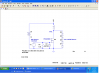
G = reluctor input
W = reluctor input
B = +12 volt logic supply
C = ignition coil (-) terminal
The metal base of the unit is the ground connection

The (+) terminal of the ignition coil goes to +12 volt supply.

I don't know what you are using this on but, you could probably use a GM reluctor made for the HEI and fabricate or use the GM magnetic star wheel.

These modules are commonly refered to as a "4 pin HEI module". Junkyards have tons of them for $1 or $2 each, new ones from a parts store are about $15.

The coil should have a low resistance primary of about 0.6 ohms. You could even salvage a GM coil while you get a module and reluctor.

Search for an MC3334, its an old IC that is the heart of the HEI module. I couldn't find a link, just a pdf to download, but it's out there. You can also search for HEI, you'll see many occurances of my "HEI mod" for Ford Probes and Mazda MX-6's.

The circuit shown in post #30 is promising.
Q1 is not a logic level mosfet so it will need quite a bit of reluctor voltage to fully turn it on (like 7v). The stack of 4001's help a lot but it may not be enough. To get a large reluctor output, you'll need a small gap to the magnet, a strong magnet, and/or a fast moving magnet. A Logic Level IRLxxxx might work better.
Q1/R2 only allows about 20ma of current to the base of Q2 and the resistor R3 across it. That's not alot. Make the R3 resistor across Q2's B-E as large as allowed to force more of that 20ma into Q2 to turn it on harder.
I forgot what I was going to say about Q3, it couldn't have been too important:)
 
Last edited:
Thanks for reply you guys, Jaguar, i m from India and not able to find GM HIE in junk market or in spare market. as Indian Gov. opened car market for other manufacturer in late 90s.
But we can try making this schematic which i posted and found here only by posting a link from other guy "shortbus".
One more question about "R5" it is large size in mm i think, is it possible to find smaller in size too?
 
Starting from the top at +15v, Q2 when turned on will have a little voltage drop across E-C, maybe 0.5v or so, R5 is 50 ohms, Q3 is a darlington (two transistors feeding one another) so it will have about a 1.4v drop across B-E to gnd. 15-0.5 = 14.5. 14.5 - 1.4 = 13.1 volts which will be dropped across R5. P = (E^2)/R = (13.1^2)/50 = about 3.5 watts. You must use at least a 2:1 power derating so R5 will need to be 7 watts minimum. 7w is not a common value for a power resistor, but 10w is, so there ya go. You might be able to find 7.5w resistors but you'll have to order them. 50 ohms is not a standard value, 47 is though, so 47 might be easier to find. You can put equal value resistors of lesser wattage in series or parallel to obtain 50/47 ohms. The power will split equally among them. If you don't use equal value resistors, the power split gets a tad more complicated but not unsurmountable.

If you would like, I can send you an HEI module. You would need to pay me the $15 or so that it costs if you want a new one, or I'll get a used one and send it for free. The advantage of the used one lies in the fact that it probably is a genuine GM part which, even though its 25 years old, it was built to higher quality standards than a new aftermarket unit.
 
Last edited:
Dear Joe, Thanks for your offer. it so kind of you. but i think we should try to make one before get readymade, if we succeed making our own it will help others too because many people facing same contact breaker problem in here. if we fail or will not get exact output as desired i will go for second option and will ask for your used one option. afterall used one will be genuine and quality product.
I have ordered parts from local market and will get today or tomorrow and will take time of 2 hours for assambe and will give you feedback tomorrow. until thn you may also try to solve the parts mystery of that patented schematic in post 24, which seems so compact too.
 
@easy.rahil - Here are more ideas; https://www.5bears.com/tim4.htm With a transistor type module that takes points, it generally will work even if the points are not in real good shape. The points are no longer switching the whole load of the coil, just the small load of the transistor circuit.
 
dear Shortbus, i have found that TIM4 is very nice but problem is that it has 3 points for Hall sensor and i dont know how to add hall sensor in all these three pins.
Okay! i have found a very useful link from youtube and i hope and i think you all have to watch once. it has parts value and schematic and video also.
just confused about parts wattage only if anybody can tell me.
here is screen and youtube link:

screen
**broken link removed**
 
Last edited:
That 2SD1071 is a great device for that type of circuit. Besides not doing anything anyhow, the 1N4007 across its C-E is redundant- the 2SD1071 has a built diode across C-E doing the same nothing.
I'm not following why this needs the start up delay. When the vehicle is first energized, the reluctor will not be producing any voltage because the star wheel is not rotating. With no reluctor output, the 1071 base will be at 0v thus the 1071 is cutoff so there is no current flowing through the coil which means no spark.
This circuit, like most of the others here do not have any current limiting for the coil primary. You will need to carefully select your coil and may also need a ballast resistor.
Coil dwell is also not addressed. Unless you use an intelligent coil driver (HEI) or yucky old points, there might not be a lot of spark energy.
 
Haven't seen any with FETs.:D
 

Attachments

  • ign.PNG
    ign.PNG
    60.6 KB · Views: 1,380
Thank you Joe, it is a nice review of that pinoy schematic.
Thank you Ron, its a real small circuit. does this works too? perfectly? i m gonna give this a first try. please give detailed information about reliability.
Thanks and waiting for all visitor give opinion.
 
Status
Not open for further replies.

Latest threads

New Articles From Microcontroller Tips

Back
Top