Continue to Site

Welcome to our site!

Electro Tech is an online community (with over 170,000 members) who enjoy talking about and building electronic circuits, projects and gadgets. To participate you need to register. Registration is free. Click here to register now.

  • Welcome to our site! Electro Tech is an online community (with over 170,000 members) who enjoy talking about and building electronic circuits, projects and gadgets. To participate you need to register. Registration is free. Click here to register now.

Transistor Ignition shematic

Status
Not open for further replies.

easy.rahil

Member
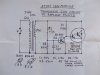
Transistor Ignition schematic

Hello All Experts, i m in need of Transistor Ignition to replace point breaker from my motorcycle. i read many many articles in internet google and almost all forums but did not yet found working and simples smallest circuit yet. and which i found they dont have answers about parts of any other related question and most of thm copid and old and parts hardly available in market.
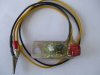
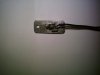
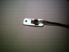
one i found recently in an another forum is seems good and using hall senser but thread owner do not reply and not giving parts list and schematic.
here it is the pic:
**broken link removed**

if anybody can help making this or magnetic trigger schematic, will be appreciated.
Thanks
 
Last edited:
The small transistor like packages are probably the Hall Effect sensors from someone like Honeywell (SS466A?). It looks like these are used to pick up the magnetic field of a rotating magnet (that cylindrical silver thing) and are used to drive the big TO220 transistors (cannot see the part number). The other packages are diodes and resistors. Unfortunately I cannot give you any more circuit detail than that
 
thanks for reply.
you are right it is of hall sensor TCi module. and ofcourse it is very small and compact too. with static timing.
May be someone else can give design with parts info so i can make it complete and test.
 
Somewhere out in "internetland" there is a simple circuit for a transistorized ignition that used one PNP power transistor. It still used breaker points, but it would be very simple to adapt the base input to work with a Hall sensor or the like. I'm sorry I never saved the web address, but its out there. If I could find it, anyone can. I bought all of the parts to build it along with a small box to house it. I sold the bike and moved and I don't know if I saved any of that stuff or not. If I can find it you can have it for a very low price.
 
O thats very nice if it ll be possible. i will find simple circuit with minimum components if it is possible that we can remove contact breaker in transistor ignition. there are some available on net with contact breaker for pulse.
 
Here is a link to an easy way to do it if you still have points. The points don't carry any real load, they just trigger the module, so points will last forever.

**broken link removed**
 
Is it a magneto type ignition? (Coil & points under flywheel) if it is I have a circuit to replace the points in this type of ignition.
 
Dear Debe, yes it is the same you are saying. you may share the design/components w ith us. hope it will help me to replace points.
 
Hi rahil, here is the circuit & pictures of a copy of an Ign module that used to be avalable but nolonger produced. To fit it you remove the Ign points & condencer & fit this module in its place. The original units were called ATOM ign modules. They are easily built & work well on the engines ihave fitted them to.
 

Attachments

  • IGN Mod2.JPG
    IGN Mod2.JPG
    114.2 KB · Views: 5,562
  • IGN Mod.JPG
    IGN Mod.JPG
    111.9 KB · Views: 2,705
  • IGN Mod7.JPG
    IGN Mod7.JPG
    110 KB · Views: 1,969
  • IGN Mod8.JPG
    IGN Mod8.JPG
    111.1 KB · Views: 2,026
  • IGN Mod4.JPG
    IGN Mod4.JPG
    112.6 KB · Views: 2,813
  • IGN Mod6.JPG
    IGN Mod6.JPG
    112 KB · Views: 1,688
Dear Debe, Thanks for your post, it is really informative and wonderful. i have few question regarding this schematic aas i m dumb at electronics. i will use pulse trigger for triggering. where to connect the input of signal? the schematic you attached has no input point for signal also need which point is Negative side and what is positive side of wires/connections.
one thing is sure that it is so compact and will give it a try as parts are cheap here in India.
i m online in yahoo and google too if possible you to chat with me. ( rahil.smart at gmail and easy_rahil at yah00 )
 
The Ign coil trigers the module, PW is the primary winding of the Ign coil. the lower part of the circuit is Gnd & the upper part is where the Points were conected. Picture of the original Module instructions. When mounting Q1 to aluminum heat sink it must be insulated.
 

Attachments

  • ATOM IGN Inst2.JPG
    ATOM IGN Inst2.JPG
    109.1 KB · Views: 2,406
Last edited:
dear Debe, thanks for your update. it is instructions material. i m in need of wire connection in schematic. and negative positive reference please.
 
The electronics doesnt get any simpler than this, sugest you find a freind who can assemble it for you. Its nearly midnight here im of to bed.
 
I have issues with the following, in the schematic :-
1) The BD649 is shorting the coil primary
2) The +ve and -ve supply connection points should be specified
3) The trigger input (R2?) is shorted to the coil primary
 
Dear Alek, your questions are perfect and i m also waiting to solve this schematic. i test this online and it says it has 2 bad connections. it will be nice if we know exact connection input and outputs.
 
Computer simulation programs arent proof that a circuit will work. This circuit definitely works & i have built several of them. If you want a full explination of how it works Google US Patents 4,163,437 Aug.7, 1979. There are 30 pages on how the circuit works & the circuit but there is no values shown, that part I had to work out. (ATOM Ign module)
 
Last edited:
Some pics of a unit before seting in resin.
 

Attachments

  • IGN Mod10.JPG
    IGN Mod10.JPG
    121.3 KB · Views: 1,209
  • IGN Mod11.JPG
    IGN Mod11.JPG
    121.8 KB · Views: 1,139
Dear Debe, I believe that you have done this job already as i can see homemade product made by you. i have a question...every system take pulse for trigger and which point take pulse in this schematic? as this module has only two wires as output or input. we can say that we need three points as:
1=Input trigger
2=output for HT coil
3=Ground
so please let me know which one is what. it will be easy for me to built.
 
There is only 2 conections, the Colector of Q1 goes to the coil conection that the points went to. The Emitter of Q1 goes to Ground. In the above picture the Brown wire goes to coil primary that went to the points. The Blue wire goes to Ground.
 
Status
Not open for further replies.

New Articles From Microcontroller Tips

Back
Top