Continue to Site

Welcome to our site!

Electro Tech is an online community (with over 170,000 members) who enjoy talking about and building electronic circuits, projects and gadgets. To participate you need to register. Registration is free. Click here to register now.

  • Welcome to our site! Electro Tech is an online community (with over 170,000 members) who enjoy talking about and building electronic circuits, projects and gadgets. To participate you need to register. Registration is free. Click here to register now.

Transistor Ignition Modules

Status
Not open for further replies.
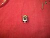
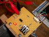
I picked up some things from the "Shack". I have to modify the heat sink they had. It is way larger than the MOSFET we are using. And I have to use a screw and washer to secure it to the heat sink

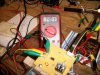
The Power supply I'm using is 13.8 V and 3 amps.. As listed on the label. I measured 14.0 V from my multimeter. I tried to take a amp reading and it was jumping all over the place, like from 9.1 down to .4.. Not sure what that was about.

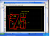
I have two options for laying it all out.. I picked up a bread board and jumpers.. and a circuit board.

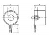
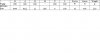
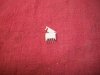
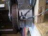
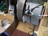
I also attached some of the info for the coil I need to build. The Chinese coil is 12v and .42 amps I don't think I can get it apart with out totally destroying it LOL
 

Attachments

  • Coil Design1a.pdf
    38.8 KB · Views: 327
If that is how your Chinese coil is made, that is why you aren't getting the power you expected :) That is a solenoid coil, the main magnetic force is in the middle of the center tube. The magnetism on the outside of it is just incidental.

As an experiment take the largest hex head bolt that will fit through the Chinese coil and then apply your power to it. Then try and attract some thing iron to the head of the bolt. It should be much more magnetic than before the bolt was inserted.

You need what is called a "E" core coil. Basically a center core connected to a end cap and a outer sleeve connected to the same end cap. The inter core and outer sleeve should be slightly longer than the coil length and all of the added parts should be iron/steel.

Think of the magnet used in a scrap yard on the crane that moves the scrap.

Here is a link to a 200 pound lift magnet that is powered by four 'C' cells! https://www.google.com/products/cat...=X&ei=SlfqTb6CG6jj0QGPg4GVAQ&ved=0CEgQ8wIwAg#

Not trying to be a smart a$$ just trying to help with your project

https://en.wikipedia.org/wiki/Electromagnet

**broken link removed**

https://www.google.com/search?q=rec...ox&ie=UTF-8&oe=UTF-8&sourceid=ie7&rlz=1I7GWYE
 
I think shortbus is right the center core needs to be solid. Your DOM pipe would probably work for the outside return path. The trick is how to make a good return path with hardware store parts. I think it should be soft steel and the top cap needs to fit really well with the pipe. What is the center core diameter on your Chinese coil? What is the thickness of the return path wall. (see my picture)This will perhaps give an idea on the sizes to keep the steel from saturating. Are you by any chance able to machine parts?
 
Have been following this thread from the beginning and have another thing I've been wondering about.

What is the original cylinder of the compressor made of? If it's magnetic, what will the effect of that be on the movement?

The magnets on the piston will partially magnetize the cylinder as will the Coil when activated. Just the magnetizing of the cylinder sleeve will add drag to free movement of the piston, won't it?

And as a worse case, would the coil after a while won't the magnets on the piston start to de-magnetize from the coil magnetizing the cylinder? Even Neo-magnets don't start out magnetic, they are made magnetic by an electric pulse.
 
shortbus,
That is not how the Chinese coil is made, what I posted was the start of my concept coil for our project.

The picture I posted is representative of some basic measurements I have to maintain to meet the constraints of the motor we are using in this project. I will be building a final coil that will include a metal shaft and plate matching the magnet dia. that is fixed to the top of the piston. That will be used to control the distance between the opposing magnets to vary the repelling force of the magnets.

For now I will build a coil with a solid core till we determine the strength requirements needed to get the motor to rotate consistently.

The current cylinder sleeve is a thin metal sleeve with a lip that is held in place by a thick paper gasket and four bolts and washers. I have thought about the possible effects the finish coil and magnets may have on the current metal sleeve and I have a few ideas to make a non metallic (PVC) or non magnetic (as in stainless steel or Aluminum) that I could use if problems arise.

Thanks for the links you posted, I will check them out once I get done with the Honey-Do-List I have for this weekend.

RonV,
The Neo magnet on the piston may indeed degrade over time, and alot of different things could contribute to that. One thing I can think of is the steel cylinder sleeve.

As for the coil.. I'm not sure if I should make a plastic/PVC spool then wind it then pack the center with a steel rod or make a steel spool, wind it then put a steel rod in the center. I know we have to consider all this but I still need to build the circuit and a way to mount the reflective switch so it can be adjustable to make timing adjustments. Then we will tackle the coil construction.

Here is the info on the Chinese coil I bought:
Electromagnet Solenoid
49mm OD, 21mm height
12VDC
Power:10W
Weight:250g
Holding/lift: 40kg
Type:HCNE1-P49/21

Here is some more info:
 

Attachments

  • Chinese Coil Info.jpg
    Chinese Coil Info.jpg
    18.6 KB · Views: 204
  • Chinese Coil Specifications.jpg
    Chinese Coil Specifications.jpg
    34.6 KB · Views: 202
Last edited:
Coil

I like the idea of putting the magnet on the top of the piston. I think this would let us not worry about a return path for the electromagnet. I bet you can find some soft steel rod and just put a layer of tape around it, a couple of plastic washers pressed and glued to the ends. Then you can wind it and put the whole ting in some PVC pipe.
I'll work on a better picture of the parts hook up. You can test the circuit and sensor without the coil to start.
 
Coil circuit

Here is a better picture for the circuit board. The LED should light when the sensor sees the reflector.

We won't need a heat-sink for 3 amps.
 

Attachments

  • maglayout.PNG
    maglayout.PNG
    120.7 KB · Views: 159
Last edited:
Circuit & Coil

RonV,
Thanks for the better circuit wiring layout. That helps alot!

I thought I would use some 1" PVC pipe and pack it full of cut clothes hanger rod.
Then make some ends 2 1/4" dia. to form a spool. I can pick up some PVC sheet from the hobby store and the glue. I have a buddy at work that is deep into making models and he can tell me exactly what kind of glue to get because regular pvc glue won't work for the end pieces because there isn't enough surface area for the glue to bite on.

I may have to just go with 2" dia. end pieces to be able to slide it into a piece of 2" pvc pipe then drill some holes in it so heat can escape. I know the coil will generate some heat. I just want to keep it as cool as possible.
 
Try to keep the core insulator as thin as you can because the further away from the core the turn is the less effective. I read a length 2X the radius is about the best you can do. So I guess for this case 2X2? Let me know when you decide on the core diameter and I'll find the wire size for bifilar winding it.
PS Magnet wire ain't cheap!
 
What does the PS mean. I found a 1300 foot spool of 26 Gauge AWG, 200C, Enameled Coper wire for around $22.00 and $5 for S/H. The lower the gauge (fatter the wire) the more it will cost for sure. But with the larget gauge wire you need less turns and the resistance is less as well.. So I have been told..

I will try to get the circuit done this week. The new circuit board layout you sent me makes it alot easier to understand.. Do you think there is a certain gauge wire I chould use for the jumper wires? I know I told you that my power supply was only 3 amps.. do you think we should just step things up to a regular 12v battery or just stick to the power supply?
 
I think 22 or 24 gage should be fine for the board.
I think the 3 amps will be ok as well. we should have 6X the current and at least 2X the number of turns over your Chinese magnet.
1300 feet should be more than enough. I think we will end up around 22 awg.
 
Circuit Parts

Ron,
I'm laying out the circuit board and I have a few questions..

1) Is there a specific way the 7,5K resistor needs to go? The color bands are red, red, black, green, purple.. What I mean is, I know that some of those things have to go in a certain direction the current can flow right.

2) Same question for the two 510s, colors are purple, black, black, purple and green

3) Do I need heatsink paste (probably calling this the wrong thing) between the 4809 and the heat sink. I know you said I may not need it, but I had already set that up.

4) Is there a specific side of the circuit board that the components go on and a certain side that you should solder on.

Here are some pictures of the four wire connector I pulled from an old piece of equipment that I want to use for the connections from the sensor. The other picture is of the heat sink I had already put together.

Kevin
 

Attachments

  • Heat Sink.jpg
    Heat Sink.jpg
    229.7 KB · Views: 164
  • 4 Wire Connector.jpg
    4 Wire Connector.jpg
    419.6 KB · Views: 157
The resistors can go in either direction. I'm not sure what kind of board you got, but I usually put the components on the side wit no traces. Looks like you are almost there.:)
 
One side has like a little "L" shapes in a few places and it is shiny. The other side was dull and no markings.. I really didn't think it matters but then again I haven't built a circuit board from scratch before. My board is just plain jane, the kind with only holes set up in it.
 
Last edited:
Sounds like a regular pre-drilled board with no copper traces, so it doesn't matter which side you use.
 
Circuit Parts are Mounted

RonV,
I got the circuit board put together this evening. From the wiring layout you did for me to wire the components together, I noticed that there are 4 leads for the sensor (blue, white, orange and green), white and orange are connected by a short jumper on the board. So i twisted them together and put them in the same location as indicated for the orange lead placement.

I thought I could just wire in the sensor as indicated, apply the (GND and +12) power connections from my power supply, connect the red and black leads from the multi meter then pass something reflective in front of the sensor and see a voltage reading at the meter.. No such luck.

So how do I test the circuit?

Kevin
 
Hi Kevin,
I think I would put everything together except leave the coil out to start with. Then when you place the reflective tape in front of the sensor the LED should light. But having said that the blue lead should go to +12 volts when the reflector is in front of the sensor. Where did you put the meter?
 
Project Update

Today I made the bracket to mount the sensor, mounted the sensor and mounted the circuit board to the wooden stand in an effort to get all the parts centrally located.

I got the LED to light by connecting the blue wire straight to the 12v input lead on the board. Look at the picture for the wiring. The green and orange sensor wires are still in the original location but the white sensor wire had to go in the location that the blue wire use to be in. The LED stays on all the time though, meaning that the circuit is staying open I guess? I may have to check the circuit connection wires because I'm not getting 12V from the circuit board where it was suppose to be..

I did manage to get a reading on the meter from the "coil" pin locations (yellow and green wires) on the board (14.00 V reading on the meter) but I'm sure that was due to the circuit staying open.

No mater what combination of wiring I tried to do the only way I could get the LED to light was from the wiring connections i already mentioned.

I used a sharpy to blacken the back side of the flywheel then mounted the reflective aluminum tape on the flywheel and moved the flywheel to see if that might trip the sensor, but no luck. The picture isn't the best but you'll get the what I'm talking about.

I had to user stranded 16 gauge wire to do the circuit connections. I hope that isn't whats not making the circuit function correctly?

I also hot glued the Neo Magnet to the top of the piston today as well.

A busy day for sure! :D
Kevin
 

Attachments

  • LED Lighted and Wiring.jpg
    LED Lighted and Wiring.jpg
    334.1 KB · Views: 193
  • Sensor Bracket.jpg
    Sensor Bracket.jpg
    310.2 KB · Views: 146
  • Reflective Tape.jpg
    Reflective Tape.jpg
    365.9 KB · Views: 203
  • Coil Leads Reading.jpg
    Coil Leads Reading.jpg
    346.6 KB · Views: 198
Last edited:
It looks like the blue and the white wires were reversed. Hope we didn't zap it.
 
So do I put the white wire on 12v now? And the blue back where it was? Nothing really came in the package that said how to connect it, I just went off the connections you laid out for me. Is there a way to test it to see if it is zapped?
 
Last edited:
Status
Not open for further replies.

Latest threads

Back
Top