Continue to Site

Welcome to our site!

Electro Tech is an online community (with over 170,000 members) who enjoy talking about and building electronic circuits, projects and gadgets. To participate you need to register. Registration is free. Click here to register now.

  • Welcome to our site! Electro Tech is an online community (with over 170,000 members) who enjoy talking about and building electronic circuits, projects and gadgets. To participate you need to register. Registration is free. Click here to register now.

Transistor Ignition Modules

Status
Not open for further replies.
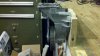
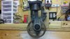
The "Electric" Compressor Motor Being Used..

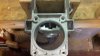
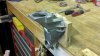
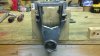
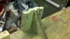
I have taken a host of pictures so that you can get an idea of what my son and I are working on.
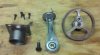
Here is the first set of 3 pictures That shows the moving parts:
Sorry the pictures are the greatest quality, I took them using my Droid Cell phone.
 

Attachments

  • Main Moving Parts1.jpg
    Main Moving Parts1.jpg
    233.8 KB · Views: 173
  • Piston components.jpg
    Piston components.jpg
    97.9 KB · Views: 189
  • I.5 x .250 N42 Magnets.jpg
    I.5 x .250 N42 Magnets.jpg
    139.8 KB · Views: 169
Last edited:
These pictures show the electric compressor chassis.
In the first picture (front view) you'll notice a hole in the bottom, that is where the flywheel and support bearings sit. The larger hole in the middle is where I had to cut out the burnt up electric motor and electric motor bearing mount.
The follow on pictures are just taken different angles.
 

Attachments

  • Chassis2.jpg
    Chassis2.jpg
    143.6 KB · Views: 186
  • Compressor Motor Chassis.jpg
    Compressor Motor Chassis.jpg
    283.3 KB · Views: 210
  • Chassis3 Piston Sleeve Opening.jpg
    Chassis3 Piston Sleeve Opening.jpg
    62.6 KB · Views: 177
  • Side View of Assembly.jpg
    Side View of Assembly.jpg
    85.4 KB · Views: 190
These last pictures show the moving parts all assembled. It is a super simple assembly. I made a wooden bracket so I would have something to mount the chassis to and a way to mount it on the bench.
 

Attachments

  • All Parts Assembled.jpg
    All Parts Assembled.jpg
    232.3 KB · Views: 196
  • Mounted to Bench.jpg
    Mounted to Bench.jpg
    121 KB · Views: 192
Last edited:
Pretty cool. Seems like it should work. I put a picture in post #19 but it probably doesn't mean much without knowing what the parts look like. I sent you a pm. If you send me your e-mail I'll send you a parts list with datasheets so you can see if you think you can build it from the picture.
 
The whole assembly turns freely once you have everything aligned. All the bearings are sealed so no worries on slinging oil on the electrical parts. Yes I replied to your PM.. I will have to get a good picture of the flywheel from the side so you can really see the profile, then I'll explain my idea for using a slitted optical sensor.. I might need some assistance picking that out.. Little steps first! LOL Besides my electromagnet still hasn't made it here from China yet!
 
I sent the link with the parts. My bet is the reflective sensor will work good. Then you can set the timing by adding or cutting the reflective tape. I added an LED so you will be able to see when the magnet is energized. If you would rather use the slotted sensor we can probably find one.
 
Ron,
Thanks for all this assistance.. I will just stick with what you have done up to this point.. I will get that working and go from there. Do I need to add a piece of circuit board to the order to mount all components on or is that something I should just slide by radio shack and pick up?
 
Radio shack is probably cheaper and should work fine.
Keep in touch!
 
Ron,
I ordered the parts last night from Mouser and they processed the order this afternoon. I think I might just make a PCB instead of trying to solder all those jumper wires. I can get all the materials to make the board for around $20.00, then I just have to drill out all the holes.

I got to looking at Free/Shareware PCB Design software on line at work today.. What program did you use to make the circuit for me? It was cool to see that some of the programs had the flexibility to move the circuit components around and they still maintained their perspective connections. Does the program you used have the ability to make a printable circuit that can be transferred to PnP film?

It seems that one thing always leads to another learning point for me.. this is so cool! I'm sure we will be talking more once i get the parts in.

Kevin
 
Last edited:
I use expresspcb. It is simple and intuitive. There a better ones like Eagle but it has more of a learning curve. I think both are free so you can play with both.
But, if you have a small soldering iron I think I would stick with the jumpers for a prototype.
 
Ordered Electromagnet

I got the China made electromagnet in last night after waiting for two weeks.. What a waste of time and a big disappointment! In fact my N42 magnets were stronger than the electromagnet. I'm glad it wasn't very expensive or I would be really mad.. But one never knows until they try.

Moving on with the project.. I should have the circuit components in tonight or tomorrow evening. Then I’ll swing by the trusty ole’ RadioShack and pick up a circuit board and fire up the soldiering iron!

Then I’ll need to build a coil from scratch. Which means making a coil winder.. No huge task, just another project for my son and I to do together.

Building a coil has been the tricky part. That was the reason I went with buying the electromagnet. And to get a base line for the coil strength I would need for the coil to function as needed. Now it seems I will need to make a coil. I know for our project the coil can only be about 2” in dia. so It can clear the bolts that hold the piston sleeve in place. I will have to work on a CAD drawing so I can post my idea for you guys to see.
 
I don't know much about magnets. Maybe someone else has some ideas. Is the problem that there is not much attraction from a distance?
I'm wondering if you could put one of your magnets on the top of the piston and then repel it when it gets to the top.
From what I can see on the net you may not do much better than your 88 lbs with a 2" magnet.
 
Last edited:
The problem is that the electromagnet I got was really weak.. it was labeled at 12v and could hold 88lbs.. but when I put the current to it it barely attracted a screwdriver. It should have almost jumped off the table to the screwdriver at 1.5 inches away.. The electromagnet got really warm quickly as well.. which could possibly mean a short in the winding as well..

I got the parts in for the ignition circuit I need to build.. so tomorrow I'll print off the stuff you sent me and stop by radio shack on the way home and pick up a circuit board.. I can make the jumper wires from wire I already have.

I'm sure I'll be asking you for some assistance.. DO you think I'll need a heat sink for the MOFSET?
 
Might not be a bad idea to get a small heat-sink in case we need "MORE POWER". Right now the circuit is over powered.
Do you have a big old transformer around that you could use the wire from to wind a coil?
 
I do have a old transformer, I've had it for like 20 years.. I drug it with me all over to convert 220v to 110v.. but it also made a few trips to Iraq with me and I am unsure of the condition of the wire.. I can just order some some enameled wire, it isn't too costly for the size coil I have to make.. Did you have a specific wire gauge in mind? I was thinking maybe 26 gauge wire and winding it in a bifilar fashion I will have twice as many conductors in the coil..
 
Last edited:
Hmmm. Well we can figure out the best wire size, but we will need to know how much current you 12 volt power supply can provide. Do you have it's ratings. I think it can be made for intermittent duty since it will only be on for a short portion of the cycle. You will need to be real careful not to stop it in the on position however. So maybe we can start with a 1/2 inch core. and a 1.9 inch diameter and work from there? It's all about amp turns so the bifilar winding is a good idea. Your china coil is probably around 15 ohms so maybe we can target 4 times as much current say 4 amps (If your supply can do that much.) Just thinking out loud again. I have no idea at what level the core will saturate, but I guess we will find out.
 
Ron,
I didn't think of asking.. But can you assist with some information on the circuit you developed?
In my search for info on the coil I have to build. I have found there are specific pieces of information needed to determine the performance and design of a coil. This is where some of the probable output from the circuit is needed..
We know we want to power and pass 12 VDC, but what might the output Watts and amps work out to?
I will pull an amp reading from my power supply that I’ll be using to power this thing up and let you know as I’m sure you need that info as well. I know we haven’t talked about it prior to now, as my layman brain was just thinking “Oh it is only 12 Volts”. I have learned that a lot of things come into play (amps, watts, volts [AC or DC], frequency [Hz]) and a few others I can’t remember off the top of my head.. And they all affect each other.

LOL we are starting to think alike! It is scary! LMAO

I will take a ohm reading on the China coil tonight as well and let you know!
 
Last edited:
Magnet

The circuit can run on a supply of 12 volts and a current of 10 amps or so with a heatsink.
I think you coil is about 10 watts- so about .8 amps. The rule of thumb for the coil running continuous is about .5 watts per square inch of surface area. But I think we can do much more because it will only be on for 10 or 20% of the time. That is where I guessed at 48 watts or 4 amps at 12 volts. We can chose the wire size to get the desired current with the most turns.
Will your Chinese magnet come apart? I'm not sure what can be used for the return path, so it would be nice just to rewind your magnet with the bifilar winding and slightly larger wire. (see picture)
 

Attachments

  • magnet.PNG
    magnet.PNG
    72.3 KB · Views: 157
I will pick up a heatsink and other items on the way home. As for the electromagnet I already have.. It was only $20 bucks and it really isn't serving my needs, so I'm willing to see if we can get her apart. the one I have is only 49MM in dia. and roughly 1" tall (give or take a little). I get exact info on it and the other stuff i mentioned once I get home.
 
Status
Not open for further replies.

New Articles From Microcontroller Tips

Back
Top