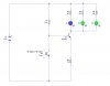
Hello all, i have my end of year exam in a few weeks and i'm running through a transistor biasing circuit that i made up just to see if i get it. The schematic is included, i just wanna run through this and make sure i'm right, and ask some questions. I'v breadboarded it and it works mostly.
Ok,
Assuming that the blue led = 4v, green led = 2v,
Ie=Ic,
The phototransistor has a measured range of 10k ohms at bright light and 1M ohms plus in darkness.
The circuit is supposed to be off during light, and light the leds (turn on) at night.
Vb = Q2/(R1 + Q2) All x Vcc
= 1M ohm/(2.2kohm + 1Mohm) all x 4.8v
Vb = 4.7v
Ve = VB - 0.6v
Ve = 4.7v - 0.6v = 4.1v
Ie = assuming i want 60ma to distribute through 3 leds (R2 for current control, i think?)
R2 = Ve/Ie
= 4.1v/0.060A
R2 = 68ohms
ie=ic so ic = 60ma
R3 = vcc-blue led/20ma(desired)
=4.8v-4v/0.020A
=40 ohms
R4 = vcc-green led/20ma(desired)
=4.8v-2v/0.020A
= 140ohms
R5 = R4 = 140ohms
Ok, I breadboarded the circuit and simulated it in livewire. The circuit simulates fine, led's go off when Q2 is reduced, on when Q2 increases.
Led's reduce slightly on breadboard in full light, dark causes led's to be on full.
Questions:
1. Does the biasing set up seem correct? I seem to think i'm missing something.
2. For R2, i assumed i needed 60ma, so is it right to do this for the value of R2? for example, say i needed ie=ic=20ma, would i just do ve/0.020 = R2?
3. How would i improve the circuit to have a better 'snap on' time? for example, on the breadboard the leds are on in decent light, how would i modify ciruit so that they would be off unless Q2 was 1Mohm ish?
Thanx for taking the time to read that.
Ross
")
