Continue to Site

Welcome to our site!

Electro Tech is an online community (with over 170,000 members) who enjoy talking about and building electronic circuits, projects and gadgets. To participate you need to register. Registration is free. Click here to register now.

  • Welcome to our site! Electro Tech is an online community (with over 170,000 members) who enjoy talking about and building electronic circuits, projects and gadgets. To participate you need to register. Registration is free. Click here to register now.

Transistor astable multivibrator problem

Status
Not open for further replies.

Letniq

New Member
Hello,
I'm new to electronic things so my problem may look stupid.
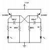
I'm trying to make an astable multivibrator so It switch between two devices via two optron couples and triac.
I've made a a little scheme without the optrons but only with two leds so I can test it. The problem is that the transistors don't want to fully turn off and so the leds don't want to turn off too. They just get brighter when they should be turned on and get less bright when they should be turned off. Here is the scheme of my circuit.
I hope someone can tell me where is my mistake.
 

Attachments

  • flasher2.jpg
    flasher2.jpg
    17.4 KB · Views: 1,937
Last edited:
Your capacitors are connected backwards, and you need diodes connected to your transistor bases to protect your transistors from damaging spikes.
 
What do you mean by backwards?
The negative poles of capacitor goes to base of the transistor. It's like this on all schemes of astable multivibrators I saw on the net.
 
You were probably looking at schematics of multivibrators that used NPN transistors, in which case connecting the negative pole to the base would be correct. In reality, it's not important which transistor lead connects to which capacitor lead. It's important the the positive cap lead connects to the more positive part of the circuit, which in your case, is the transistor base. Think of which way current will flow into the cap. Positive current should flow into the positive lead.
 
Last edited:
Also, to get your transistors to turn completely off/on, you need to lower the value of your 500K base bias resitors.
 
I started the circuit using this scheme as reference.
**broken link removed**
 
Last edited:
A few transistor multivibrator oscillators on the net are shown with the polarity of the capacitors backwards. The wire of each capacitor that connects to the base of the PNP transistors is near the posistive supply voltage and the capacitor wire at the collectors goes to a much lower voltage.

The circuits are also shown with the supply voltage too high (like your circuit) which causes avalanche breakdown of the reverse-biased emitter-base junction of the transistors. Diodes can prevent the avalanche breakdown.
 
Now your diodes are connected backwards. And 500K is probably too high for the base resistors.
 
Last edited:
The 2200uf capacitors might have too much leakage current for 100k base resistors.
You can use capacitors with a lower value that have a lower leakage current then a digital divider IC to produce the very low frequency.
 
Last edited:
My idea is to control the time the device are turned on via 100K trimmers. I need achieve time aprox. 20sec to 120sec.
If you have different ideas how to achieve it. Please share. :)
 
I recommend a 555 timer circuit. Cycle times of 10 or more minutes are easy when using these devices. Here is a good **broken link removed**
 
Last edited:
A CD4060 IC has an oscillator with a digital divider and can time for a fairly long time with a small timing capacitor in its oscillator.
A CD4541 is a programmable timer IC also with an oscillator and a digital divider and has many features.
 
The 2200uf capacitors might have too much leakage current for 100k base resistors.
You can use capacitors with a lower value that have a lower leakage current then a digital divider IC to produce the very low frequency.

A better solution is to use Darlingtons so the resistor values can be higher and capacitors smaller, or normal transistors and a transistor buffer to power the device: I'll post a schematic if anyone's interested.

MOSFETs should also work but I've never built an astable with MOSFETs.
 
Actually now I'm using a 555 and a relay with fixed timing. The problem is that I couldn't control the high and low state time independently. After a search on the internet I've found a way to do it.

**broken link removed**
555 Timer Tutorials

If I understood right I can use two trimmers instead Ra and Rb and the time device 1 is on will depend on the trimmer 1 and the time device 2 is on will depend on trimmer 2.
Am I right?
 
Status
Not open for further replies.

New Articles From Microcontroller Tips

Back
Top